
An electronic dehumidifier

A dehumidifier and electronic technology, applied in the direction of household heating, lighting and heating equipment, noise suppression, etc., can solve the problems of poor sealing performance, difficulty in achieving satisfactory results, and low dryness, and achieve safe and convenient use and low noise , The effect of low equipment price

Active Publication Date: 2018-02-09
GUANGXI UNIV
View PDF5 Cites 1 Cited by
  • Summary
  • Abstract
  • Description
  • Claims
  • Application Information

AI Technical Summary

Problems solved by technology

When facing a closet or a smaller space, the dehumidifier is usually made in a small size according to the existing temperature difference principle, but the sealing performance is poor, and it is easy to become a source of moisture, especially for valuables and small spaces where there is insufficient moisture removal and moisture resistance. The degree is not high, it is difficult to achieve satisfactory results

Method used


Image

  • An electronic dehumidifier

Examples


Embodiment Construction

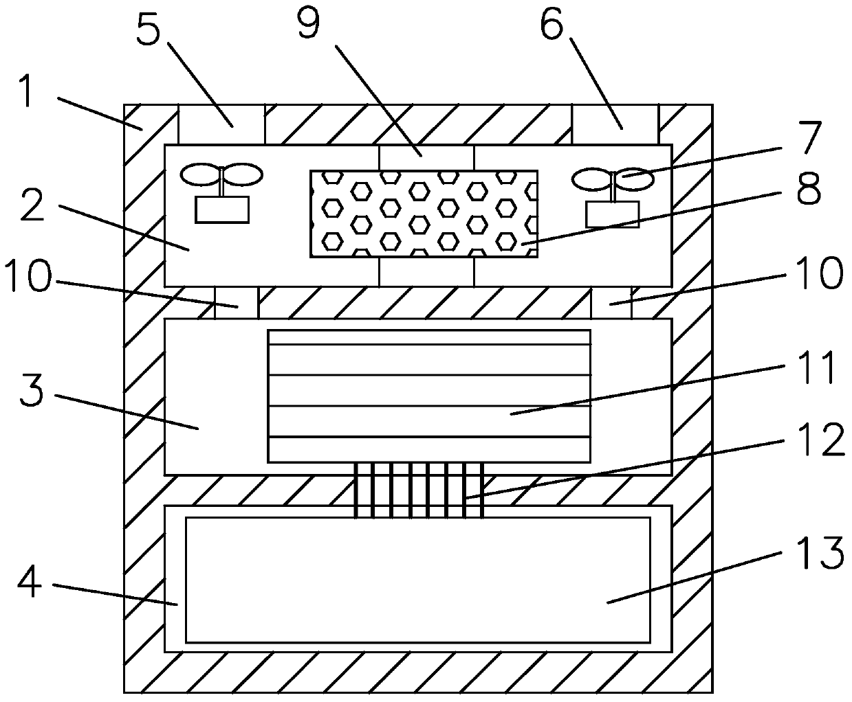
[0015] The invention discloses an electronic dehumidifier, comprising a casing 1, the casing 1 includes a dehumidification passage 2, a cooling passage 3 and a water storage box 4; The tuyeres 6 are equipped with fans 7 respectively, and a porous dry material 8 is placed in the middle of the dehumidification channel 2, and the circumference of the porous dry material 8 is a heater 9; the cooling channel 3 communicates with the cooling channel 3 end to end through a valve 10, and the cooling channel 3 A plurality of electronic cooling chips 11 are installed, and a plurality of capillary tubes 12 are arranged on the cooling channels 3 around the electronic cooling chips 11 to communicate with the water storage box 4 , and a water-absorbing material 13 is placed in the water storage box 4 .

[0016] It specifically includes three modules: dehumidification channel 2, cooling channel 3 and water storage box 4; two and two cycles: dry air circulation and. Among them, the dehumidific...


PUM


Abstract

The invention relates to the technical field of indoor dehumidification equipment, in particular to an electronic dehumidifier. The electronic dehumidifier comprises a shell. The shell internally comprises a dehumidification channel, a cooling channel and a water storage box. Fans are installed at an air inlet with a valve and an air outlet with a valve of the dehumidification channel. Porous drying materials are arranged in the middle of the dehumidification channel. A heater is arranged on the circumferences of the porous drying materials. The head and tail of the cooling channel are communicated through the valves. A plurality of electronic cooling chips are installed in the cooling channel. A plurality of capillary tubes are arranged on the periphery of the electronic cooling chips of the cooling channel and are communicated with the water storage box. Water absorbing materials are arranged in the water storage box. The dehumidification speed is high; humidity is uniform; the size of the equipment is small; noise is low or basically no noise exists; the price of the equipment is low; the advantages of ultralow humidity, no humidity rebound and the like can be achieved rapidly.

Description

technical field [0001] The invention relates to the technical field of indoor dehumidification equipment, in particular to a simple electronic dehumidifier. Background technique [0002] A dehumidifier is a dehumidifier designed to improve the humid environment. It can separate the moisture in the air from the air and turn it into water to drain away. You only need to put the dehumidifier in the room and space that needs to be protected from moisture, and the humidity can be adjusted. It can be adjusted freely by yourself, and it can be managed by no one. It is also the best moisture-proof measure at present. [0003] Current household dehumidifiers are all designed to dehumidify and prevent moisture for the entire room or a larger space. When facing a closet or a smaller space, the dehumidifier is usually made in a small size according to the existing temperature difference principle, but the sealing performance is poor, and it is easy to become a source of moisture, espec...

Claims


Application Information

Patent Timeline
Patent Type & Authority Patents(China)
IPC IPC(8): F24F1/02F24F13/24
CPCF24F3/1423F24F13/24
Inventor 王威
Owner GUANGXI UNIV
Learn More