

Control method for embedded dry-burning prevention temperature sensor
A temperature sensor and control method technology, applied in the field of gas stoves, can solve the problems of small spring compression, affecting the appearance of the stove, and small contact pressure, so as to achieve the effect of increasing the lifting amount and improving the detection accuracy
- Summary
- Abstract
- Description
- Claims
- Application Information
AI Technical Summary
Problems solved by technology
Method used
Image

Examples
Embodiment 1
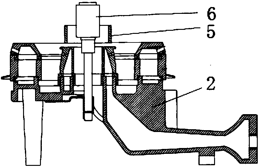
[0058] Figure 7-Figure 9 A preferred embodiment of an embedded anti-dry temperature sensor for a gas cooker according to the present invention is shown. Wherein, the temperature sensor body 6 includes an inner tube 61 and an outer end cover corresponding to the inner tube 61, the outer end cover includes a heat shield 62 and a cover part 63 connected to the heat shield 62, and a heat shield is arranged on the cover part 63. For the sensitive element, an elastic element 64, such as a spring, is arranged between the outer end cap and the inner tube 61, and a wire (not shown) connected to the thermal element is arranged in the inner tube 61.
[0059] In this embodiment, the control system includes a controller 9 (preferably an MCU controller) and a judging device for judging whether the compression of the elastic element 64 reaches a preset value. When the judging device judges that the compression of the elastic element 64 reaches a preset value, the controller 9 controls the ...
Embodiment 2
[0094] This embodiment is basically the same as Embodiment 1. For the sake of brevity, in the description process of this embodiment, the same technical features as Embodiment 1 will not be described, and only the differences between this embodiment and Embodiment 1 will be described:
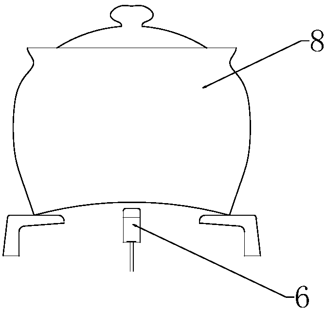
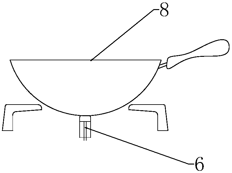
[0095] Such as Figure 15 with Figure 16 As shown, the judging device includes a limit switch 65 arranged on the inner tube 61, and a sensitive block 68 is arranged on the wire 67. When the elastic element 64 reaches a predetermined amount of compression, the sensitive block 68 on the wire 67 and the limit switch 68 Correspondingly, and trigger the limit switch 68. That is to say, when the lifting mechanism 7 drives the temperature sensor body 6 up and down, the limit switch 68 rises and falls together with the temperature sensor body 6, and when the temperature sensor body 6 touches the pot 8 during the rising process, the outer end cover stops rising, The inner tube 61 continues to rise, a...
Embodiment 3
[0107] This embodiment is basically the same as Embodiment 1. For the sake of brevity, in the description process of this embodiment, the same technical features as Embodiment 1 will not be described, and only the differences between this embodiment and Embodiment 1 will be described:
[0108] Such as Figure 18 As shown, the lifting mechanism 7C includes a fixed bracket 7C-1 for fixing the temperature sensor body 6, a cam 7C-2, and a support frame 7C-5 for supporting the cam 7C-2, and the fixed bracket 7C-1 includes a fixed bracket body , one side of the fixed bracket body is provided with a transverse chute 7C-8, and the free end of the cam 7C-2 is slidably connected with the transverse chute 7C-8.
[0109] During use, the cam 7C-2 is rotated, and the fixed bracket 7C-1 cooperating with the cam 7C-2 is driven to move up and down under the rotation of the cam 7C-2, thereby driving the temperature sensor body 6 connected with the fixed bracket 7C-1 to move up and down, Theref...
PUM
 Abstract
Description
Claims
Application Information