Corn drying device for agriculture

A drying device, corn technology, applied in drying, dryer, grain drying and other directions, can solve the problem of low drying efficiency of corn, and achieve the effects of avoiding shaking, good effect and high efficiency

Inactive Publication Date: 2018-03-30
衡阳博思科技有限公司
5 Cites 1 Cited by

AI-Extracted Technical Summary

Problems solved by technology

[0004] The purpose of the present invention is to provide an agricultural corn drying device, which has the advantages...

Method used

Please refer to Fig. 1-3, a kind of agricultural corn drying device comprises oven 1, and the bottom of oven 1 is fixedly connected with movable box 13, and the right side of oven 1 is provided with stirring motor 7 , the connection between the top and the bottom of the stirring motor 7 and the drying box 1 is fixedly connected by the support 8, and the stirring motor 7 can be fixed by the support 8, so that the stirring motor 7 has a better effect when in use, avoiding In order to prevent the shaking of the stirring motor 7 during use, resulting in poor use of the stirring motor 7, the output end of the stirring motor 7 is provided with a rotating shaft 5, and the left side of the rotating shaft 5 runs through and extends to the inside of the drying box 1. cavity, the top and bottom of the rotating shaft 5 are equipped with stirring blades 3, the number of stirring blades 3 is not less than three, and the shape and size of the three stirring blades 3 are the same, the connection between the inner side of the stirring blade 3 and the rotating shaft 5 is connected The block 4 is fixedly connected, and the present invention can fix the stirring blade 3 by connecting the block 4, so that the stirring blade 3 has a better effect when in use, and avoids the situation that the stirring blade 3 becomes loose during use, thereby causing stirring If the blade 3 is not used effectively, the surface of the rotating shaft 5 is covered with a net cage 2, and the stirring blade 3 is located in the inner cavity of the net cage 2, and the joints between both sides of the net cage 2 and the rotating shaft 5 are moved through the sliding sleeve 6 Connect, the bottom of net cage 2 is fixedly connected with movable plate 11, and the bottom of movable plate 11 runs through drying case 1 and movable case 13 and extends to the inner chamber of movable case 13, and the bottom of movable case 13 is provided with anti-skid pad 9, passes The a...

Abstract

The invention discloses a corn drying device for agriculture. The corn drying device comprises a drying box. A moving box is fixedly connected to the bottom of the drying box. A stirring motor is arranged on the right side of the drying box. A rotating shaft is arranged at the output end of the stirring motor. The left side of the rotating shaft penetrates and extends into an inner cavity of the drying box. Stirring blades are arranged on the top and the bottom of the rotating shaft correspondingly. The surface of the rotating shaft is sleeved with a screen box. The stirring blades are locatedin an inner cavity of the screen box. The two sides of the screen box and the rotating shaft are movably connected through sliding sleeves correspondingly. A moving plate is fixedly connected to thebottom of the screen box. By means of mutual cooperation of the screen box, the stirring blades, the rotating shaft, the sliding sleeves, the stirring motor, the sliding groove, the moving plate, themoving box, the sliding block, a rotating disc, the moving plate, a sliding rail and the rotating motor, when the drying device is used, the function of efficiently drying corns is achieved, and thusthe drying device is higher when being used.

Application Domain

Drying solid materialsDrying machines with non-progressive movements +1

Technology Topic

AgricultureRotating disc +1

Image

  • Corn drying device for agriculture
  • Corn drying device for agriculture
  • Corn drying device for agriculture

Examples

  • Experimental program(1)

Example Embodiment

[0017] The technical solutions in the embodiments of the present invention will be clearly and completely described below in conjunction with the accompanying drawings in the embodiments of the present invention. Obviously, the described embodiments are only a part of the embodiments of the present invention, rather than all the embodiments. Based on the embodiments of the present invention, all other embodiments obtained by those of ordinary skill in the art without creative work shall fall within the protection scope of the present invention.
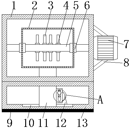
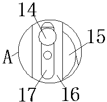
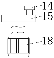
[0018] See Figure 1-3 , An agricultural corn drying device, comprising a drying box 1, a movable box 13 is fixedly connected to the bottom of the drying box 1, a stirring motor 7 is provided on the right side of the drying box 1, and the top and bottom of the stirring motor 7 are connected with The joints of the drying box 1 are all fixedly connected by the bracket 8. Through the bracket 8, the stirring motor 7 can be fixed, so that the stirring motor 7 has a better effect during use and avoids the shaking of the stirring motor 7 during use The mixing motor 7 has a bad use effect. The output end of the mixing motor 7 is provided with a rotating shaft 5. The left side of the rotating shaft 5 penetrates and extends to the inner cavity of the drying box 1. The top and bottom of the rotating shaft 5 are both There are mixing blades 3, the number of mixing blades 3 is not less than three, and the shapes and sizes of the three mixing blades 3 are the same. The connection between the inner side of the mixing blade 3 and the rotating shaft 5 is fixedly connected by the connecting block 4, and the present invention is connected The block 4 can fix the mixing blade 3, so that the mixing blade 3 has a better effect during use, and avoids the loosening of the mixing blade 3 during use, resulting in a poor use effect of the mixing blade 3. The surface of the rotating shaft 5 is sleeved with a net box 2, and the stirring blade 3 is located in the inner cavity of the net box 2. The connections between both sides of the net box 2 and the rotating shaft 5 are movably connected by sliding sleeves 6, and the bottom of the net box 2 is fixedly connected There is a moving plate 11, and the bottom of the moving plate 11 penetrates the drying box 1 and the movable box 13 and extends to the inner cavity of the movable box 13. The bottom of the movable box 13 is provided with a non-slip pad 9, through which the movable box 13 can be Play a fixed role, so that the movable box 13 has a better effect when in use, avoiding the situation that the movable box 13 is moving when in use, which leads to the situation that the movable box 13 is not effective, and the top of the anti-skid pad 9 is The joints of the boxes 13 are fixedly connected by adhesives. The bottom of the inner cavity of the movable box 13 is provided with a chute 10 adapted to the movable plate 11, and the movable plate 16 is fixedly connected to the right side of the movable plate 11. A rotating motor 18 is provided on the right side of the cavity. The connection between the bottom of the rotating motor 18 and the movable box 13 is fixedly connected by the base 12, and the rotating motor 18 can be fixed through the base 12, so that the rotating motor 18 is in use. The effect is better, and the shaking of the rotating motor 18 during use is avoided, which results in the poor use effect of the rotating motor 18. The output end of the rotating motor 18 is provided with a turntable 15 and the surface of the turntable 15 is fixedly connected with a slider 14 , The surface of the movable plate 16 is provided with a slide rail 17 that is matched with the slider 14 display. The present invention passes through the cage 2, the stirring blade 3, the rotating shaft 5, the sliding sleeve 6, the stirring motor 7, the chute 10, the moving plate 11, and the movable plate. The box 13, the sliding block 14, the turntable 15, the movable plate 16, the slide rail 17 and the rotating motor 18 cooperate with each other, which can effectively dry the corn when the drying device is in use. The efficiency is higher, which avoids the situation that the existing drying device has a single function during use, which results in the low efficiency of the drying device for drying corn, and is suitable for popularization.
[0019] When in use, the stirring motor 7 runs, the stirring motor 7 drives the rotating shaft 5 to rotate, the rotating shaft 5 drives the stirring blade 3 to rotate, the rotating motor 18 runs, the rotating motor 18 drives the turntable 15 to rotate, and the turntable 15 drives the slider 14 to rotate. The cooperation of the sliding block 14 and the sliding rail 17 drives the movable plate 16 to move left and right, and the movable plate 16 drives the movable plate 11 to move left and right. The sliding groove 10 in the movable box 13 cooperates with the movable plate 11 to move left and right, and the movable plate 11 The cage 2 is driven to move left and right, and the shaft 5 and sliding sleeve 6 cooperate with the cage 2 to move left and right to efficiently dry the corn.
[0020] To sum up: the agricultural corn drying device passes through the cage 2, the mixing blade 3, the rotating shaft 5, the sliding sleeve 6, the mixing motor 7, the chute 10, the moving plate 11, the movable box 13, the sliding block 14, and the turntable. 15. The movable plate 16, the slide rail 17 and the rotating motor 18 solve the problem of low efficiency of corn drying by the existing drying device.
[0021] Although the embodiments of the present invention have been shown and described, those of ordinary skill in the art can understand that various changes, modifications, and substitutions can be made to these embodiments without departing from the principle and spirit of the present invention. And variations, the scope of the present invention is defined by the appended claims and their equivalents.

PUM

no PUM

Description & Claims & Application Information

We can also present the details of the Description, Claims and Application information to help users get a comprehensive understanding of the technical details of the patent, such as background art, summary of invention, brief description of drawings, description of embodiments, and other original content. On the other hand, users can also determine the specific scope of protection of the technology through the list of claims; as well as understand the changes in the life cycle of the technology with the presentation of the patent timeline. Login to view more.

Similar technology patents

Systems and methods for notifying multiple hosts from an industrial controller

ActiveUS8150959B1reusable block of code very difficultimprove efficiency
Owner:ROCKWELL AUTOMATION TECH

Hybrid OLED having improved efficiency

InactiveUS20080284317A1improve efficiency
Owner:GLOBAL OLED TECH

MIMO-OFDM transmitter

InactiveUS20070253504A1improve efficiencyreduce time
Owner:FUJITSU LTD

Classification and recommendation of technical efficacy words

  • good effect
  • Improve efficiency
Why Eureka
Try Eureka