
Method for testing rod body surface shear stress of total-length bonding reinforcing steel bar anchor rod

A testing method and a technology of shear stress, which are applied in the measurement, force measurement, and measurement device of the change force of the optical properties of the material when it is stressed, can solve the problem of easy falling off of the strain gauge, low spatial resolution, and inability to anchor the steel bar To solve problems such as the monitoring of rod working properties, achieve the effect of strong anti-electromagnetic field interference, simple testing process, and strong operability

Inactive Publication Date: 2018-03-30
QINGDAO TECHNOLOGICAL UNIVERSITY
View PDF6 Cites 4 Cited by
  • Summary
  • Abstract
  • Description
  • Claims
  • Application Information

AI Technical Summary

Problems solved by technology

Existing bolt body stress test methods mainly include electrical measurement and optical fiber testing. The electrical measurement technology is to directly paste the resistance strain gauge on the surface of the bolt body. The strain gauge is easy to fall off, resulting in the loss of data during the test process. It is not reasonable enough to fully monitor the working properties of steel anchors; and optical fiber testing also includes distributed (Brillouin method, BOTDA) and quasi-distributed (Bragg grating method, Bragg Grating) two methods, distributed (Brillouin method, BOTDA) Brillouin method) uses one optical fiber for continuous testing, which is suitable for long-distance measurement. The Brillouin method can perform continuous testing in name, but the spatial resolution is low, and the accuracy of measuring point positioning can only be up to 20cm, which is not suitable for full-length bonding. Short components such as anchor rods are tested, especially the stress concentration change area near the orifice cannot be accurately located
Quasi-distributed (Bragg grating method) connects a string of grating sensors with an optical fiber and pastes them directly on the surface of the anchor rod to test the anchor rod. Because there are raised threads on the surface of the steel bar, even after polishing, the grating sensor often does not stick firmly.

Method used


Image

  • Method for testing rod body surface shear stress of total-length bonding reinforcing steel bar anchor rod
  • Method for testing rod body surface shear stress of total-length bonding reinforcing steel bar anchor rod
  • Method for testing rod body surface shear stress of total-length bonding reinforcing steel bar anchor rod

Examples


Embodiment

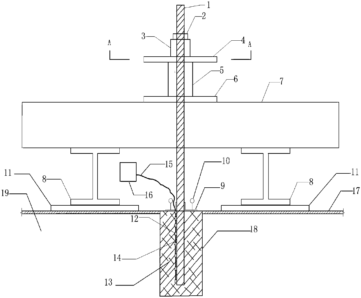
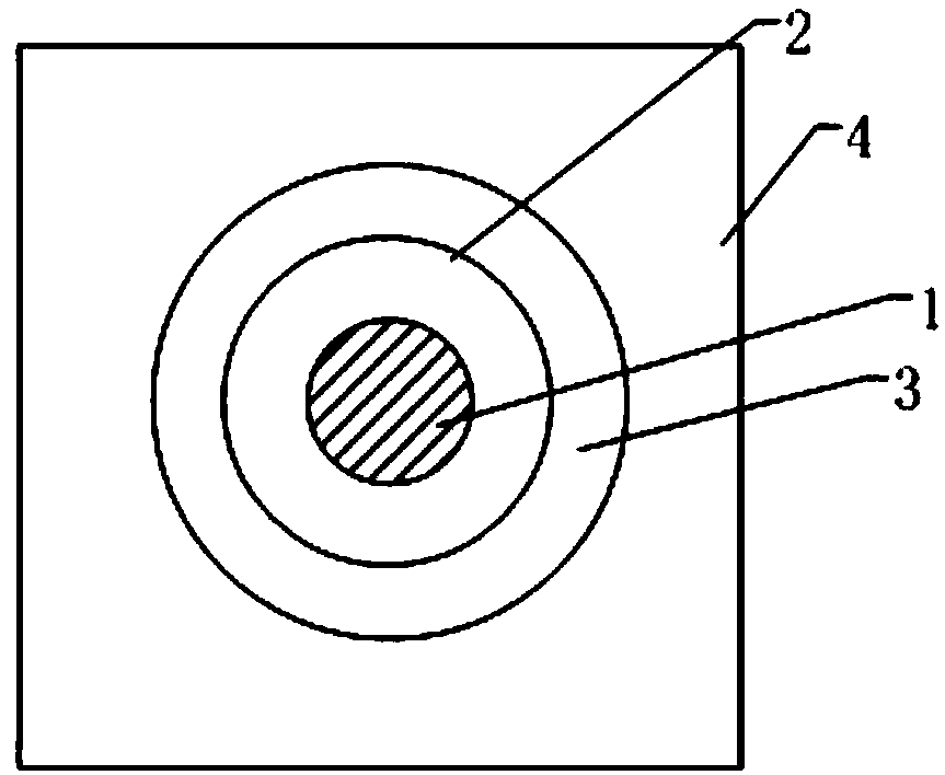
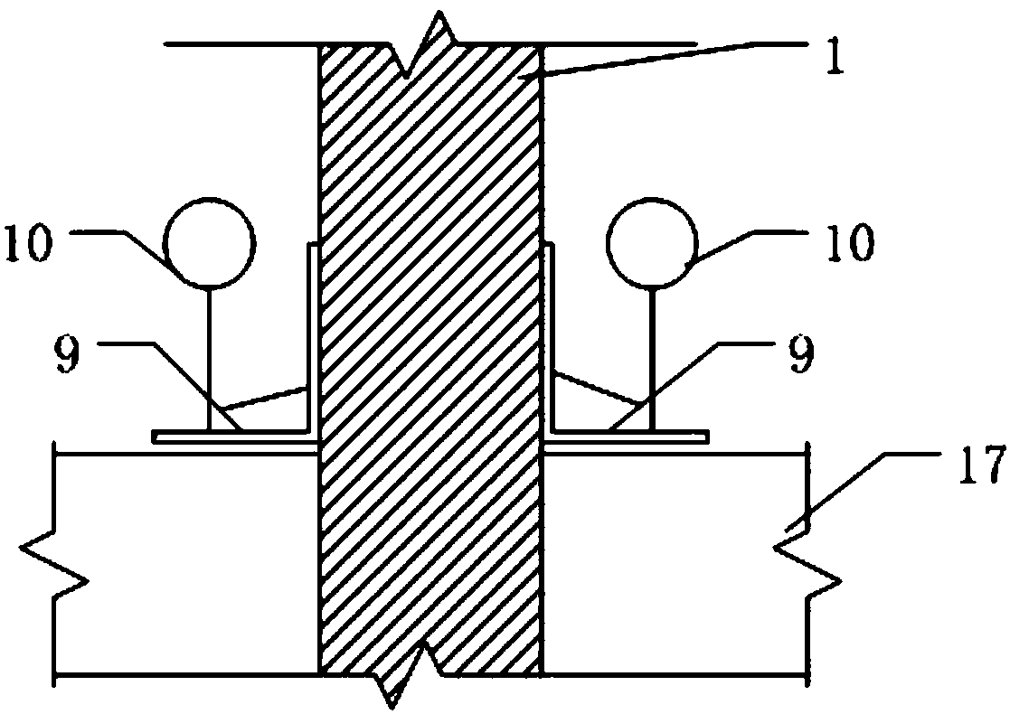
[0027] This embodiment adopts the surface shear stress testing device of the full-length bonded steel anchor rod to realize, and the specific process is as follows:

[0028](1), according to the shear stress test section of the anchor rod body 1, determine the position of the low temperature sensitive miniature fiber grating strain sensor 12, and engrave the low temperature sensitive miniature fiber grating strain sensor 12 into the optical fiber 14 to form a fiber grating sensor string. The sensor near the top of the rod hole is relatively dense), and the miniature clamping blocks at each low-temperature-sensitive miniature optical fiber grating strain sensor 12 two ends are welded on the anchor rod body 1 respectively, so that the low-temperature-sensitive miniature optical fiber grating strain sensor 12 and the anchor rod The rod body 1 is integrated to ensure that the two are deformed synchronously after being stressed, and the optical fiber 14 at the end of the anchor rod ...


PUM


Abstract

The invention belongs to the technical field of shear stress testing, and relates to a method for testing rod body shear stress of a total-length bonding reinforcing steel bar anchor rod. When a grating sensor is subjected to a tensile force or pressure effect, the grating sensor extends or compresses, so that a grating period or fiber core refractive index changes, finally, wavelength drift of the fiber bragg grating sensor is caused, and thus shear stress of the rod body surface of the reinforcing steel bar anchor rod is obtained. The method for testing rod body surface shear stress of the total-length bonding reinforcing steel bar anchor rod is simple in test technology, convenient to operate, high in test precision and operability, and high in electromagnetic field interference resistance and rate of survival, and can realize automated monitoring.

Description

Technical field: [0001] The invention belongs to the technical field of shear stress testing, and relates to a method for testing the surface shear stress of a full-length bonded steel bar anchor body, which can more accurately and conveniently obtain the surface shear stress of a full-length bonded steel bar anchor body, which is used as a design parameter for the anchor bar. Reasonable selection and revision of relevant specifications provide basis. Background technique: [0002] At present, in the process of civil engineering construction, due to the limitation of geographical location, when excavating foundation pits in some places, the area of ​​foundation pits is too large, the excavation depth is too deep, the geological conditions are complex, and the working surface outside the foundation pits In narrow and small situations, in order to ensure that the foundation pit support in this situation can meet the strength and load requirements, in the foundation pit support...

Claims


Application Information

Patent Timeline
IPC IPC(8): G01L1/24
CPCG01L1/246
Inventor 张明义白晓宇赵天杨匡政杨苏春王永洪牟洋洋苗德滋
Owner QINGDAO TECHNOLOGICAL UNIVERSITY
Learn More