Method for developing austenite grain boundary of sulfur free-machining steel through electrolytic corrosion
A technology of austenite grain boundary and electrolytic corrosion, which is used in material analysis by optical means, preparation of test samples, measurement devices, etc. The implementation process is smooth and safe, easy to control, and easy to operate.
- Summary
- Abstract
- Description
- Claims
- Application Information
AI Technical Summary
Problems solved by technology
Method used
Image

Examples
Embodiment 1
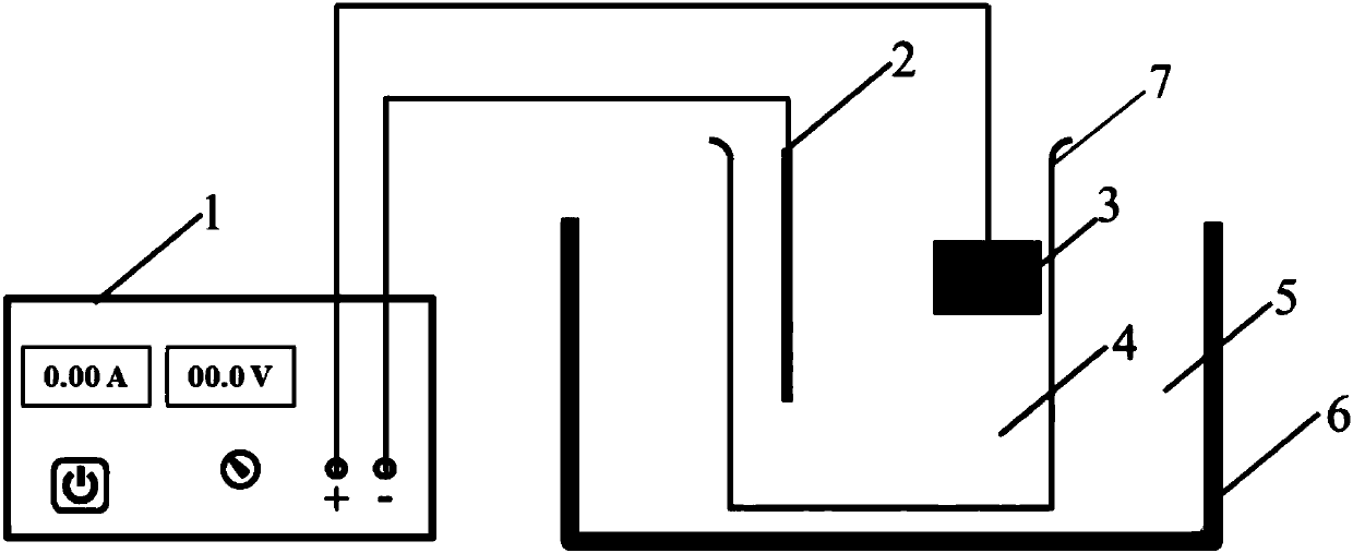
[0037] Such as figure 1 Shown: Adopt the technical scheme of the development method of the austenite grain boundary of sulfur-based free-cutting steel through electrolytic corrosion of the present invention, carry out electrolytic corrosion on the austenite grain boundary of Y08MnS sulfur-containing free-cutting steel, and observe the grain boundary , the specific implementation steps are as follows:
[0038] S1. Sample preparation: cutting and grinding sulfur-based free-cutting steel into a steel sample, cutting and grinding at least one surface of the steel sample into a smooth and scratch-free grinding surface;
[0039] Preferably, the cut steel sample in S1 is embedded in the anti-corrosion material, and the side for electrolytic corrosion is exposed.
[0040] In detail, firstly, the sulfur-based free-cutting steel is cut to an appropriate size, and then the cut steel sample 3 is embedded in a corrosion-resistant material, which can not only fix the steel sample 3, but al...
Embodiment 2
[0064] Such as figure 1 Shown: Adopt the technical scheme of the development method of the austenite grain boundary of sulfur-based free-cutting steel through electrolytic corrosion of the present invention, carry out electrolytic corrosion on the austenite grain boundary of Y08MnS sulfur-containing free-cutting steel, and observe the grain boundary , the specific implementation steps are as follows:
[0065] S1. Sample preparation: cutting and grinding sulfur-based free-cutting steel into a steel sample, cutting and grinding at least one surface of the steel sample into a smooth and scratch-free grinding surface;
[0066] Preferably, the cut steel sample in S1 is embedded in the anti-corrosion material, and the side for electrolytic corrosion is exposed.
[0067] In detail, firstly, the sulfur-based free-cutting steel is cut to an appropriate size, and then the cut steel sample 3 is embedded in a corrosion-resistant material, which can not only fix the steel sample 3, but al...
Embodiment 3
[0091] Such as figure 1 Shown: Adopt the technical scheme of the development method of the austenite grain boundary of sulfur-based free-cutting steel through electrolytic corrosion of the present invention, carry out electrolytic corrosion on the austenite grain boundary of Y08MnS sulfur-containing free-cutting steel, and observe the grain boundary , the specific implementation steps are as follows:
[0092] S1. Sample preparation: cutting and grinding sulfur-based free-cutting steel into a steel sample, cutting and grinding at least one surface of the steel sample into a smooth and scratch-free grinding surface;
[0093] Preferably, the cut steel sample in S1 is embedded in the anti-corrosion material, and the side for electrolytic corrosion is exposed.
[0094] In detail, firstly, the sulfur-based free-cutting steel is cut to an appropriate size, and then the cut steel sample 3 is embedded in a corrosion-resistant material, which can not only fix the steel sample 3, but al...
PUM
| Property | Measurement | Unit |
|---|---|---|
| current density | aaaaa | aaaaa |
| current density | aaaaa | aaaaa |
| concentration | aaaaa | aaaaa |
Abstract
Description
Claims
Application Information
 - R&D
- Intellectual Property
- Life Sciences
- Materials
- Tech Scout
- Unparalleled Data Quality
- Higher Quality Content
- 60% Fewer Hallucinations
Browse by: Latest US Patents, China's latest patents, Technical Efficacy Thesaurus, Application Domain, Technology Topic, Popular Technical Reports.
© 2025 PatSnap. All rights reserved.Legal|Privacy policy|Modern Slavery Act Transparency Statement|Sitemap|About US| Contact US: help@patsnap.com