Color film base plate and preparation method thereof

A color filter substrate and substrate technology, applied in nonlinear optics, instruments, optics, etc., can solve the problems of stacking area height exceeding the pixel opening area height, different color color filter protrusions, display panel chromaticity deviation, etc., to strengthen the prevention The effect of the color mixing function

Active Publication Date: 2018-03-30
TCL CHINA STAR OPTOELECTRONICS TECH CO LTD
View PDF8 Cites 3 Cited by
  • Summary
  • Abstract
  • Description
  • Claims
  • Application Information

AI Technical Summary

Problems solved by technology

[0005] like Figure 1c As shown, the material of the retaining wall 102 is lyophilic. At this time, the RGB color resist 101 will form a "concave" profile with thick sides and a thin middle, and similar Figure 1a Chromaticity deviation problem in
At the same time, if it is a super-lyophilic material, similar Figure 1b inflow into other pixel areas causing color mixing issues
[0006] In addition, since the printing trajectory of inkjet printing droplets is usually not 100% accurate, it is inevitable that a small number of droplets will fall to non-target pixel areas during the printing process.
The control accuracy of the printer table is generally in the range of 3-5um. It can be seen that the printing droplets that deviate from the trajectory are more likely to drop on the retaining wall area.
Due to the fluidity of the droplets, it is very likely that the droplets on the barrier wall will flow to the adjacent pixel area, which will also cause the problem of color mixing
In addition, if the two color resists are stacked on the retaining wall, it is very likely that the height of the stacked area will exceed the height of the pixel opening area, which will affect the subsequent liquid crystal alignment due to poor flatness.
[0007] To sum up, color film substrates in the prior art are prone to color mixing when printing RGB color resists, or cause chromaticity deviations on the display panel, and the stacking of color films of different colors at the junction may easily cause protrusions and affect subsequent liquid crystal alignment.

Method used


Image

  • Color film base plate and preparation method thereof
  • Color film base plate and preparation method thereof
  • Color film base plate and preparation method thereof

Examples


Embodiment Construction

[0038] The following descriptions of the various embodiments refer to the accompanying drawings to illustrate specific embodiments in which the invention may be practiced. The directional terms mentioned in the present invention, such as [up], [down], [front], [rear], [left], [right], [inner], [outer], [side], etc., are only for reference Additional schema orientation. Therefore, the directional terms used are for describing and understanding the present invention, not for limiting the present invention. In the figures, structurally similar elements are denoted by the same reference numerals.

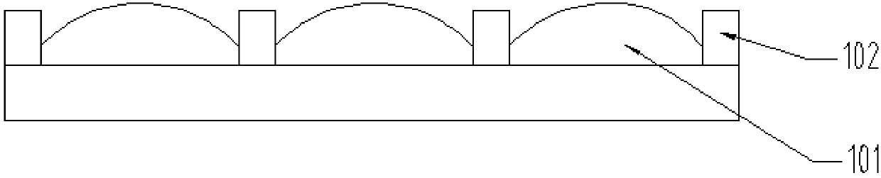
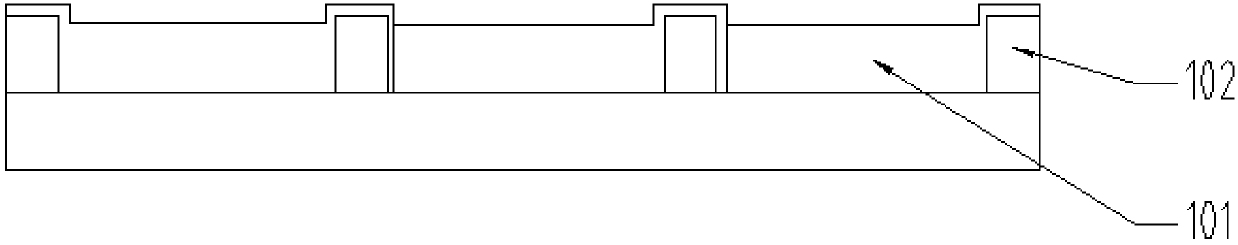
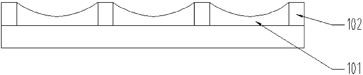
[0039] The present invention is aimed at the color filter substrate of the prior art, which is prone to color mixing when printing color resists, or leads to chromaticity deviation of the display panel, and the stacking of different color color filters at the junction is likely to cause protrusions and affect subsequent liquid crystal alignment. , this embodiment can solve this defect...


PUM

PropertyMeasurementUnit
transmittivityaaaaaaaaaa

Abstract

The invention provides a color film base plate and a preparation method thereof. The color film base plate comprises a base plate, colorful color resistances prepared on the surface of the base plate,and baffle walls prepared on the surface of the base plate and defines corresponding area of the colorful color resistances. Each of the baffle walls of different colors among the colorful color resistances at least comprises a first sub-baffle wall and a second sub-baffle wall which are parallel to each other and oppositely installed, the first sub-baffle wall has first predetermined close and distant liquidity, and the second sub-baffle wall has second predetermined close and distant liquidity; so as to solve the problem of color mixture and color deviation of a display panel when the colorful color resistances are printed.

Description

technical field [0001] The invention relates to the field of display technology, in particular to a color filter substrate and a preparation method thereof. Background technique [0002] At present, the production of TFT LCD (Thin Film Transistor Liquid Crystal Display) color filters basically uses negative photoresist coating, exposure, and development to form pixels. (Black matrix, red, green, blue and spacers) photoresist materials all cause great waste. Based on this, inkjet printing, a high-efficiency and high-resistance utilization method, has been studied for the fabrication of color filters. Inkjet printing color filters are made in the non-pixel opening area as a sidewall to prevent red, green and blue (RGB) color mixing, and then inkjet printing is used to print red, green and blue in the corresponding pixel opening area. There are three kinds of color resist inks, so that the efficient use of photoresist can be realized and the process of exposure and developmen...

Claims


Application Information

Patent Timeline
Patent Type & Authority Applications(China)
IPC IPC(8): G02F1/1335
CPCG02F1/133512G02F1/133514G02F1/133516
Inventor 饶夙缔
Owner TCL CHINA STAR OPTOELECTRONICS TECH CO LTD
Why Eureka
Try Eureka