Multistage telescopic electric cylinder

An electric cylinder and cylinder barrel technology, which is applied in the transmission field, can solve the problems of excessive bearing size, difficult assembly, and restricting the development of small-sized multi-stage electric cylinders.

Pending Publication Date: 2018-03-30
XIAN FANGYUANMING TECH CO LTD
View PDF12 Cites 14 Cited by
  • Summary
  • Abstract
  • Description
  • Claims
  • Application Information

AI Technical Summary

Problems solved by technology

However, in electric cylinders with small radial dimensions, the bearings are too larg...

Method used


Image

  • Multistage telescopic electric cylinder
  • Multistage telescopic electric cylinder

Examples


Embodiment 1

[0032] An embodiment of the present invention provides a multi-stage telescopic electric cylinder. The multi-stage telescopic electric cylinder includes: a cylinder, and the electric cylinder also includes: an N-stage transmission mechanism arranged in the cylinder and sequentially sleeved, wherein, N≥ 2. N is a natural number; the number of stages of the electric cylinder is N stages.

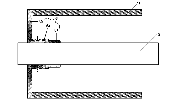
[0033] Each stage of transmission mechanism includes: lead screw, push rod and nut. Each level of nut includes: a body provided with an internal thread and an extension part arranged at the end of the body, and the extension part surrounds the opening of the body. The body is sleeved on the lead screw. The end of the extension part is fixedly connected with one end of the push rod.

[0034] Except for N-level nuts, the outer surface of the nut body of each level is provided with multiple outer annular raceways; except for the first-level screw, the inner surface of each level of screw is pro...

Embodiment 2

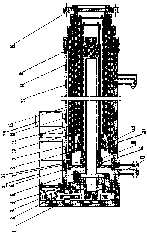
[0056] In order to illustrate the multi-stage telescopic electric cylinder provided by the present invention in more detail, a three-stage telescopic electric cylinder is taken as an example for specific description below.

[0057] refer to figure 1 As shown, the three-stage telescopic electric cylinder includes: a cylinder 22, and a three-stage transmission mechanism arranged in the cylinder 22 and sequentially sleeved, wherein the first-stage transmission mechanism includes: a first-stage lead screw 5, a first-stage The first stage push rod 11 and the first stage nut 6, the second stage transmission mechanism includes: the second stage lead screw 7, the second stage push rod 12 and the second stage nut 8, the third stage transmission mechanism includes: the third stage lead screw 9. The tertiary push rod 13 and the tertiary nut 10.

[0058] Each level of nut includes: a body provided with an internal thread and an extension part arranged at the end of the body, and the exte...


PUM


Abstract

The invention provides a multistage telescopic electric cylinder, relates to the field of transmission technologies, and is applicable to manufacturing multistage telescopic electric cylinders. The multistage telescopic electric cylinder comprises a cylinder barrel, N stages of transmission mechanisms, N-1 stages of balls, N-1 stages of transmission keys and N stages of guide keys. The N stages oftransmission mechanisms sequentially sleeve one another; each stage of transmission mechanism comprises a lead screw, a push rod and a nut; a body of each stage of nut sleeves the corresponding leadscrew, and the tail end of an extension portion of each stage of nut is fixedly connected with an end of the corresponding push rod; a plurality of outer annular raceways are arranged on the outer surface of the body of each stage of nut except for the N stage of nut; a plurality of inner annular raceways are arranged on the inner surface of each stage of lead screw except for the first stageof lead screw; each stage of balls is embedded in spaces between the outer annular raceways of the corresponding current stage of nut and the inner annular raceways of the corresponding next stage oflead screw. The multistage telescopic electric cylinder has the advantage that large working stroke can be provided by the multistage telescopic electric cylinder under the condition of small radial assembly dimensions.

Description

technical field [0001] The invention relates to the field of transmission technology, in particular to a multi-stage telescopic electric cylinder. Background technique [0002] The electric cylinder is a device that converts the rotary motion of the servo motor into the linear motion of the working mechanism. The electric cylinder has a simple structure and good servo control performance, and is widely used in the transmission field. [0003] Electric cylinders are divided into single-stage electric cylinders and multi-stage electric cylinders. Single-stage electric cylinders are suitable for occasions with small working strokes; multi-stage electric cylinders are suitable for occasions with large working strokes. At present, in multi-stage electric cylinders, bearings are used to connect and drive between the lead screws of each stage and the push rods of each stage. However, in electric cylinders with small radial dimensions, the bearings are too large to be assembled, ...

Claims


Application Information

Patent Timeline
IPC IPC(8): H02K7/06H02K7/10F16H25/22
CPCH02K7/06H02K7/10F16H25/2204
Inventor 白飞鹏
Owner XIAN FANGYUANMING TECH CO LTD
Why Eureka
Try Eureka