Carrier return-flow system

A carrier and track technology, applied in the directions of loading/unloading, conveyor control device, conveyor objects, etc., can solve the problem of the backflow of the carrier or the easy jamming of the space, so as to solve the problem of the backflow of the carrier or the space or easy to get stuck. Stuck, simple and practical structure, space-saving effect

Inactive Publication Date: 2018-04-03
INVENTEC CHONGQING
View PDF6 Cites 5 Cited by
  • Summary
  • Abstract
  • Description
  • Claims
  • Application Information

AI Technical Summary

Problems solved by technology

[0006] In view of the shortcomings of the prior art described above, the purpose of the present invention is to provide a carrier return system to solve the problems of carrier return or space occupation or easy jamming in the prior art

Method used


Image

  • Carrier return-flow system

Examples


Embodiment Construction

[0033] Embodiments of the present invention are described below through specific examples, and those skilled in the art can easily understand other advantages and effects of the present invention from the content disclosed in this specification. The present invention can also be implemented or applied through other different specific implementation modes, and various modifications or changes can be made to the details in this specification based on different viewpoints and applications without departing from the spirit of the present invention.

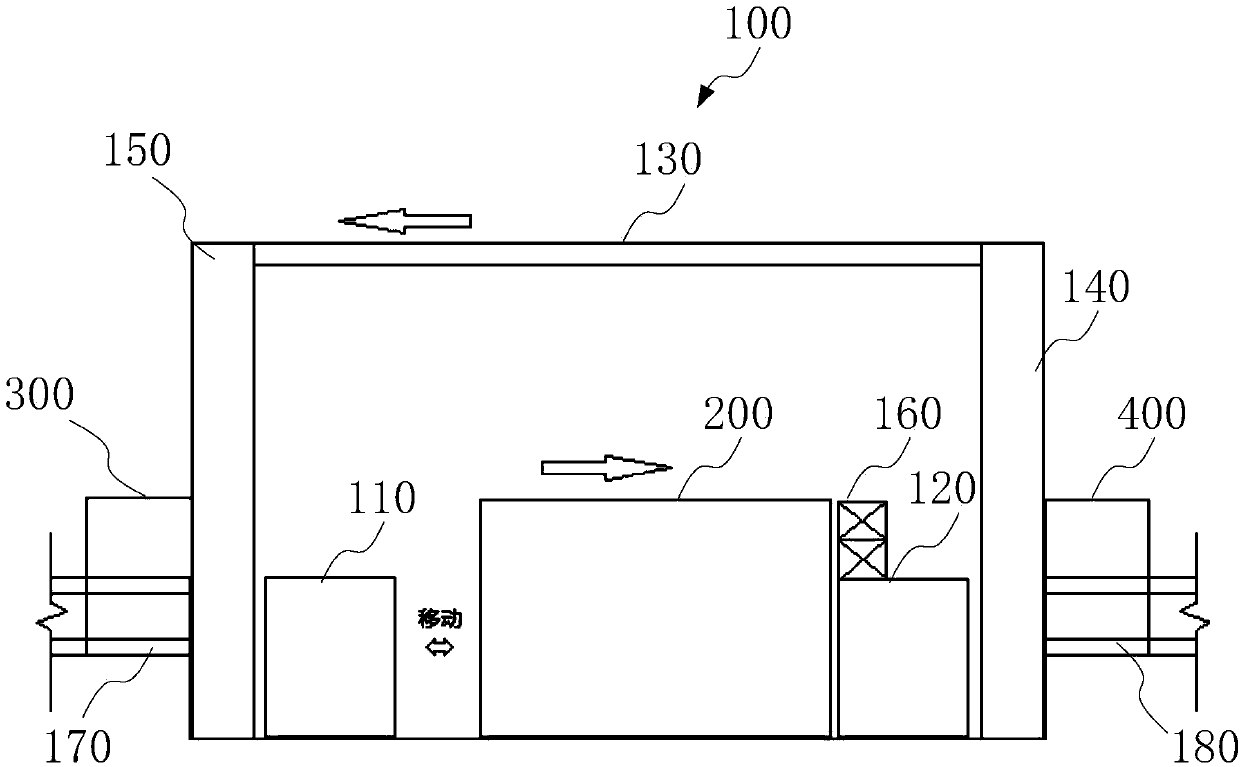
[0034] see figure 1 . It should be noted that the structures, proportions, sizes, etc. shown in the drawings attached to this specification are only used to match the content disclosed in the specification, for those who are familiar with this technology to understand and read, and are not used to limit the implementation of the present invention. Limiting conditions, so there is no technical substantive meaning, any modification of ...


PUM


Abstract

The invention provides a carrier return-flow system which comprises a feeding transmission platform, a discharging transmission platform, a return-flow rail, a first lifting mechanism, a second lifting mechanism and a controller. The feeding transmission platform bears a carrier carrying a printed circuit board and transmits the printed circuit board to the interior of a furnace body; the discharging transmission platform outputs the carrier output from the interior of the furnace body to a plate separating machine so as to separate the printed circuit board from the carrier; the return-flow rail is arranged above the furnace body and flows back the no-load carrier in the horizontal direction; the first lifting mechanism enables the no-load carrier to ascend to an inlet of the return-flowrail so as to transmit the no-load carrier to the return-flow rail; the no-load carrier on the return-flow rail descends through the second lifting mechanism to the horizontal position where the feeding transmission platform is located so as to contain the printed circuit board; and the controller is used for controlling the feeding transmission platform, the discharging transmission platform, thereturn-flow rail, the first lifting mechanism and the second lifting mechanism to run. By means of the carrier return-flow system, the problem that in the prior art, the carrier flows back or space is occupied or locking is prone to occurrence is solved.

Description

technical field [0001] The present invention relates to the technical field of data storage, in particular to the technical field of storage devices, in particular to a carrier reflow system. Background technique [0002] In recent years, with the development of automation technology, the production and testing processes of electronic products in the manufacturing industry are widely realized by assembly lines, that is, the electronic products to be produced or tested are placed on the conveyor belt of a production line, and passed through various The production or testing process mainly includes assembly production or performance testing, aging testing, etc., and the reliability of the product in harsh environments can be judged based on the results of these production or testing processes. [0003] In the production process of electronic products, the products to be produced or tested are placed on a carrier and transported to a designated place by the carrier. After the ...

Claims


Application Information

Patent Timeline
Patent Type & Authority Applications(China)
IPC IPC(8): B65G37/02B65G43/08B65G47/64B65G69/20
CPCB65G37/02B65G43/08B65G47/64B65G69/20B65G2201/0258
Inventor 张健全
Owner INVENTEC CHONGQING
Why Eureka
Try Eureka