
Winding device used for multiple flexible pipelines

A winding device and multi-flexible technology, which is applied in the directions of transportation and packaging, thin material handling, and delivery of filamentous materials, etc., can solve problems such as high cost, heavy weight of the carrying device, and unbalanced force on the working tool, and achieve cost reduction. Low, easy-to-control effects

Inactive Publication Date: 2018-04-03
XCMG CONSTR MACHINERY
View PDF7 Cites 1 Cited by
  • Summary
  • Abstract
  • Description
  • Claims
  • Application Information

AI Technical Summary

Problems solved by technology

[0004] 1) Put the hydraulic pipe and the mud pipe in two independent capstans respectively. The hoses wound in the two capstans are not synchronized, and the tension on the hoses is also different, which will easily cause the working tools connected to the hoses to be damaged. The unbalanced force causes the deflection of the slot hole formed by the construction of the working tool;
[0005] 2) It is necessary to control two independent winches so that they can move synchronously with the working tool, which is complex to control, technically difficult and costly;
[0006] 3) The carrying device is heavy, the manufacturing cost of the equipment is high, the power consumption of driving the equipment is large, and the transportation is inconvenient;
[0007] 4) In the process of disassembly and assembly, two winches need to be disassembled and assembled separately. The time of high-altitude operation is long and the risk is high.

Method used


Image

  • Winding device used for multiple flexible pipelines
  • Winding device used for multiple flexible pipelines
  • Winding device used for multiple flexible pipelines

Examples


Embodiment 1

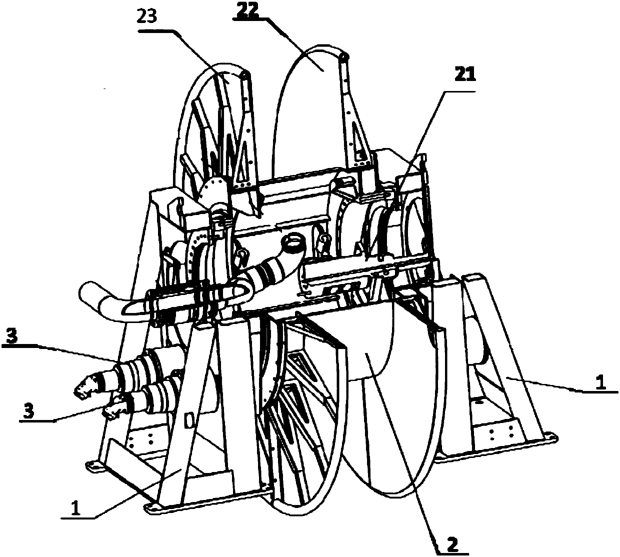
[0035] Such as figure 1 As shown, a winding device for multi-flexible pipelines, including a support 1, a rotating part 2 and several porous pipe clamps 4;

[0036] The rotating member 2 is arranged on the supporting member 1, and can rotate around the supporting member 1, and is used for winding the pipeline; in one implementation of this embodiment, the rotating member 2 can be realized by using a reel; figure 2 As shown, in the embodiment of the invention, the rotating member 2 is connected to the supporting member 1 (a support frame can be selected) in a manner supported at both ends, and the driving device 3 (a motor, etc., which can be The device for driving) drives to rotate around the rotation axis 21 of the rotating member 2;

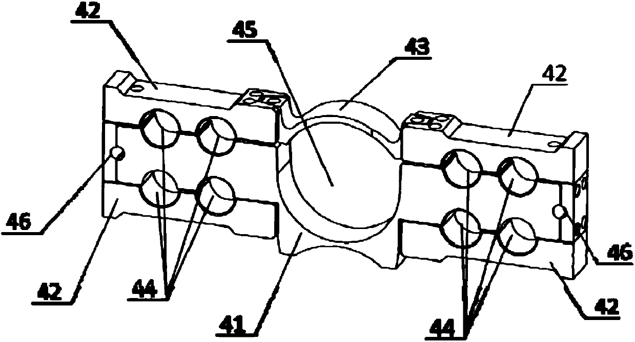
[0037] The porous pipe clamp 4 includes a connection support body 41 and several cover plates; the connection support body 41 is provided with several grooves of different sizes; the number of the grooves is the same or different from the num...

Embodiment 2

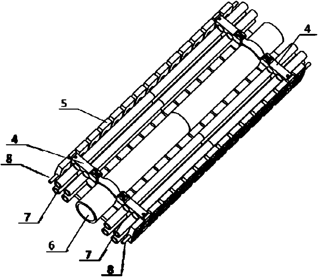
[0042] Based on embodiment 1, in the embodiment of the present invention, such as Figure 3-5As shown, in order to prevent the upper and lower layers of pipelines in the rotary member 2 from being squeezed against each other, the winding device for multi-flexible pipelines also includes several spacers 5; the spacers 5 are arranged between two adjacent porous pipe clamps 4, it is connected with the corresponding porous pipe clamp 4 through a guide 8 (preferably a guide rope), and is neatly arranged between each porous pipe clamp 4 without rotation deflection; during specific implementation, the spacer block 5 and the corresponding positions on the two ends 51 of the porous pipe clamp 4 are all provided with through holes (see figure 2 46 in and Figure 5 54) is used for the passage of the guide member 8, and at least two guide ropes are provided between the spacer block 5 and the porous pipe clamp 4; during actual work: the guide rope passes through the porous pipe clamp 4 a...

Embodiment 3

[0047] Based on Embodiment 1 or Embodiment 2, in the embodiment of the present invention, the rotating member 2 is a reel, and the two sides of the rotating member 2 in the axial direction are respectively provided with a first baffle 22 and a second baffle 23 (The first baffle plate 22 and the second baffle plate 23 can be installed on the rotating member 2 by bolts), the first baffle plate 22 and the second baffle plate are parallel to each other, and the extension direction of the two is in line with the rotation direction. The extension direction of the piece 2 is vertical, and the rotating arrow can be rotated forward and backward to retract the hose line (not shown in the figure). The first baffle plate 22 and the second baffle plate 23 are used to limit the pipeline wound on the rotating piece 2 from outward shift.

[0048] In summary:

[0049] The invention provides a winding device for multi-flexible pipelines, which can place multiple hoses of different sizes (such ...


PUM

PropertyMeasurementUnit
Diameteraaaaaaaaaa
Diameteraaaaaaaaaa

Abstract

The invention discloses a winding device used for multiple flexible pipelines. The winding device comprises a supporting part, a rotary part and a plurality of multi-hole pipe clamps, wherein the rotary part is arranged on the supporting part, and can automatically rotate around the supporting part; each multi-hole pipe clamp comprises a connecting supporting body and a plurality of cover plates;a plurality of grooves of different dimensions are formed in each connecting supporting body; the quantity of the grooves is same with or different from that of the cover plates; the cover plates areopposite to the corresponding grooves in each connecting supporting body to form a plurality of slot holes for allowing pipelines to pass through; and the multi-hole pipe clamps are arranged in an extending direction of the pipelines for fixing the pipelines into one row. According to the winding device used for multiple flexible pipelines disclosed by the invention, various pipelines with relatively great diameter difference are fixedly arranged into a chain row through the multi-hole pipe clamps, and the whole chain row is wound into one rotary part; and single rotary part is controlled to extend and retract in a rotary mode, so that the problem that pipeline winding by multiple rotary parts in the prior art is out of step is solved.

Description

technical field [0001] The invention belongs to the technical field of pile machinery, and in particular relates to a winding device for multi-flexible pipelines. Background technique [0002] For soil digging tools, such as double-wheel milling machines, pipe jacking machines, etc., when these tools are digging holes in the soil, they need to transmit power to the tool through the hydraulic pipeline to drive the teeth on the tool The soil is stripped, and at the same time, the mud pump on the working tool is driven to discharge the stripped soil and mud mixture through the hose. With the continuous digging operation of the work tool, the distance between the work tool and the power source gradually increases, and the required length of the hose is also larger. Therefore, it is often necessary to arrange a winding device (usually a hose winch) for taking in and taking out a long hose. [0003] The current common form of winch is: put hoses with the same or similar diameter...

Claims


Application Information

Patent Timeline
IPC IPC(8): B65H54/553B65H54/74B65H75/14B65H75/18
CPCB65H54/553B65H54/74B65H75/14B65H75/18B65H2701/33
Inventor 倪坤郑文关庆宇
Owner XCMG CONSTR MACHINERY
Learn More