
Dehumidifier

A dehumidifier and wet channel technology, applied in the field of air conditioners, can solve the problem of high air temperature at the air outlet

Inactive Publication Date: 2018-04-03
GREE ELECTRIC APPLIANCES INC
View PDF6 Cites 1 Cited by
  • Summary
  • Abstract
  • Description
  • Claims
  • Application Information

AI Technical Summary

Problems solved by technology

[0004] The invention provides a dehumidifier to solve the technical problem of high air temperature at the air outlet of the dehumidifier in the prior art

Method used


Image

  • Dehumidifier
  • Dehumidifier
  • Dehumidifier

Examples


Embodiment Construction

[0023] The following will clearly and completely describe the technical solutions in the embodiments of the present invention with reference to the accompanying drawings in the embodiments of the present invention. Obviously, the described embodiments are only some, not all, embodiments of the present invention. The following description of at least one exemplary embodiment is merely illustrative in nature and in no way taken as limiting the invention, its application or uses. Based on the embodiments of the present invention, all other embodiments obtained by persons of ordinary skill in the art without creative efforts fall within the protection scope of the present invention.

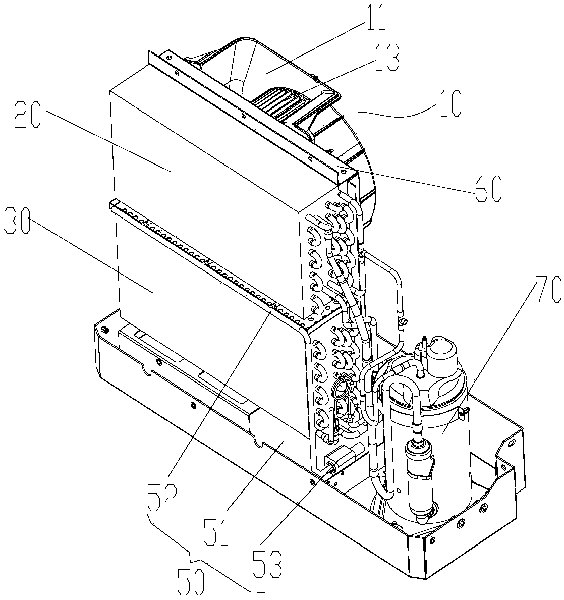
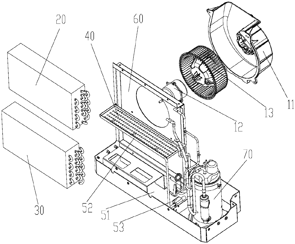
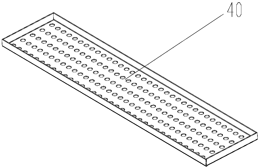
[0024] Such as Figure 1 to Figure 4 As shown, the present invention provides a dehumidifier. The dehumidifier includes: a housing, a fan assembly 10 , an evaporator 20 and a condenser 30 . Wherein, the casing has a first air inlet, a first air outlet, and a dehumidification channel respectively co...


PUM


Abstract

The invention provides a dehumidifier which comprises a shell, a fan blade assembly, an evaporator and a condenser, wherein the shell is provided with a first air inlet, a first air outlet and a dehumidification channel communicating with the first air inlet and the first air outlet; the fan blade assembly is arranged in the dehumidification channel and is used for feeding to-be-dehumidified air into the dehumidification channel from the first air inlet and discharging the air out of the first air outlet; the evaporator is arranged in the dehumidification channel and is used for removing watervapour on the to-be-dehumidified air; the condenser is arranged in the dehumidification channel and is positioned below the evaporator ; the evaporator communicates with the condenser through a refrigerant pipeline; and condensate water formed when the water vapour is condensed via the evaporator is used for having heat exchange with the condenser. With adoption of the technical scheme, the technical problem in the prior art that the temperature of the air at the air outlet of the dehumidifier is higher is solved.

Description

technical field [0001] The invention relates to the technical field of air conditioners, in particular to a dehumidifier. Background technique [0002] At present, dehumidifiers generally have four major parts of conventional refrigeration equipment, namely compressor, throttling element, evaporator and condenser. When the dehumidifier performs dehumidification work, the compressor compresses the refrigerant to promote the flow of the refrigerant between the components. After the refrigerant flows out of the compressor, it first passes through the condenser, and the condenser transfers the heat of the high-temperature refrigerant to the air. Generally speaking, the air temperature near the condenser is as high as 40°C; The low-temperature refrigerant then enters the evaporator, making the surface temperature of the evaporator reach the dew point temperature of the air, which is about 18°C. The water vapor in the air immediately condenses on the fin surface of the evaporator...

Claims


Application Information

Patent Timeline
IPC IPC(8): F24F1/02F24F3/14F24F11/89F24F13/30F24F13/22
CPCF24F1/02F24F3/1405F24F13/222F24F13/30F24F2003/1446
Inventor 温德平李华本张建鹏
Owner GREE ELECTRIC APPLIANCES INC
Learn More