Air separator for refrigerating

A technology of air separator and air inlet, which is applied in the direction of refrigeration, liquefaction, liquefaction, solidification, etc. It can solve the problems of many connecting elbows, large resistance along the process, and low heat exchange efficiency, so as to improve work efficiency and reduce stroke resistance and reduce clogging effect

Inactive Publication Date: 2018-04-03
潜江传家电子商务有限公司
View PDF0 Cites 1 Cited by
  • Summary
  • Abstract
  • Description
  • Claims
  • Application Information

AI Technical Summary

Problems solved by technology

[0003] At present, the air separators in common refrigeration systems mainly include horizontal quadruple casing type and vertical helical tube type. Incomplete heating, excessive loss of refrigerant, etc.

Method used


Image

  • Air separator for refrigerating
  • Air separator for refrigerating

Examples


Embodiment Construction

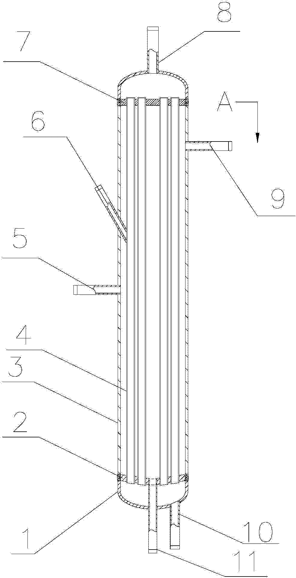
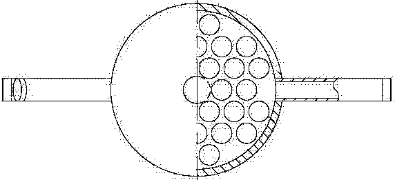
[0015] The air separator of the present invention belongs to heat exchange and purification equipment, and is suitable for removing air and other non-condensable gases in a refrigeration system. The invention improves on the shortcomings of the traditional quadruple sleeve type and spiral heat exchange tube type air separators, and mainly improves the heat exchange elements in the shell into heat exchange tubes with compact structure and triangular arrangement. Compared with the traditional air separator, it reduces the occupied space of the air separator, increases the condensation heat exchange area, improves the condensation cooling efficiency, and speeds up the discharge of non-condensable gas. In addition, the invention has the advantages of simple structure, easy manufacture, long service life, and wide application range. Using the high-efficiency air separator designed by the invention can enhance the heat exchange and purification capacity of the refrigeration system an...


PUM


Abstract

The invention provides an air separator for refrigeration, which includes a head, a lower tube plate, a cylinder body, a plurality of heat exchange tubes, a mixed gas inlet, a temperature probe socket, an upper tube plate, a liquid outlet, an outlet Air port, liquid supply pipe and condensate outlet; among them, the liquid supply pipe and condensate outlet are located at the bottom of the cylinder, and the liquid outlet is located at the top of the cylinder; the heat exchange tube is connected with the upper tube sheet and the lower tube sheet, and the The body is arranged in a triangle; the mixed gas inlet is located in the middle of one side of the cylinder, and the gas outlet is located in the upper part of the other side of the cylinder; low-temperature refrigerant circulates in the heat exchange tube. The invention can remove air and other non-condensable gases in the refrigeration system, improves the efficiency of the refrigeration system, and achieves the purpose of energy-saving operation of the refrigeration system.

Description

technical field [0001] The invention relates to the technical field of heat exchange and purification equipment, in particular to an air separator for refrigeration. Background technique [0002] During the operation of the refrigeration system, although the refrigeration device uses a closed cycle system to operate, it is inevitable that air will be released when the refrigeration system operates under negative pressure, such as refueling, adding refrigerant, opening the shaft seal of the compressor, and opening the valve stem. Into the closed system, and the lubricating oil will also decompose into non-condensable gas under the action of high temperature. If there is a large amount of non-condensable gas in the system, the pressure of the high-pressure condensing system will increase, the power consumption of the compressor motor will increase, the cooling capacity will decrease, and the operating efficiency of the system will decrease. In severe cases, it may even endange...

Claims


Application Information

Patent Timeline
Patent Type & Authority Applications(China)
IPC IPC(8): F25J3/04
CPCF25J3/04187
Inventor 不公告发明人
Owner 潜江传家电子商务有限公司
Why Eureka
Try Eureka