Data transmission indication and processing method and device
A data transmission and indication technology, applied in the direction of synchronization devices, electrical components, wireless communication, etc., can solve problems such as data conflicts of different lengths of TTI
- Summary
- Abstract
- Description
- Claims
- Application Information
AI Technical Summary
Problems solved by technology
Method used
Image
Examples
Embodiment 1
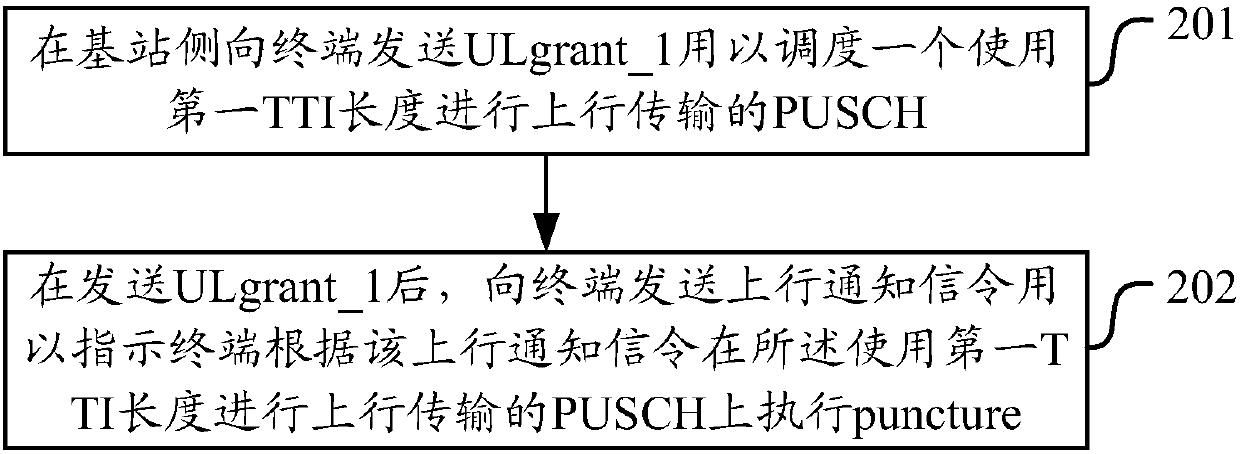
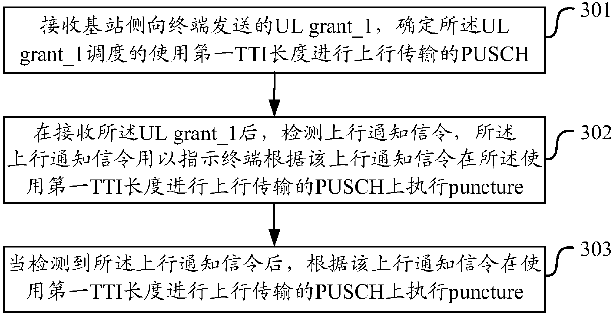
[0198] Figure 6 It is a schematic diagram of how the base station instructs the PUSCH of the terminal 1 to make a puncture, as shown in the figure, assuming that the base station is in the traditional control area of the downlink subframe n (occupying the first 1-4 OFDM (Orthogonal Frequency Division Multiplex, orthogonal frequency division multiplex) of a subframe frequency division multiplexing) symbol) to send UL grant_1 to instruct Terminal 1 to schedule a PUSCH with a 1ms length TTI transmission, assuming that the 1ms length TTI PUSCH scheduled by the UL grant_1 according to a certain scheduling sequence is transmitted on the uplink subframe n+4, and the base station In downlink subframe n+3, use shortened DCI (short DCI) to send UL grant_2 to schedule a TTI with a length of 2 symbols to transmit PUSCH. This short TTI data is in the 8th and 9th symbol positions of the 1ms length TTI in uplink subframe n+4 Transmission and frequency resources completely overlap.
[019...
Embodiment 2
[0203] Figure 7 A schematic diagram of puncture indicating the PUSCH of Terminal 1 for the base station in Embodiment 2, as shown in Figure 7 As shown, it is assumed that the base station sends UL grant_1 in the traditional control area of downlink subframe n to instruct terminal 1 to schedule a PUSCH with a length of 1 ms TTI transmission. For transmission on +4, the base station sends a UL grant_2 scheduling TTI with a length of 2 symbols to transmit PUSCH in the traditional control area in the downlink subframe n+3. This short TTI data is in the 13th TTI of 1ms length in the uplink subframe n+4 , Transmission at 14 symbol positions, and frequency resources completely overlap. The base station chooses to send the notification signaling P while sending the UL grant_2 in the traditional control area of the downlink subframe n+3. The indication field of the notification signaling P is 6-bit information, and the first 4 bits indicate the starting symbol position of the pu...
Embodiment 3
[0207] Figure 8 A schematic diagram of puncture indicating the PUSCH of Terminal 1 for the base station in Embodiment 3, as shown in Figure 8 As shown, it is assumed that the base station sends UL grant_1 in the traditional control area of downlink subframe n to instruct terminal 1 to schedule a PUSCH with a length of 1 ms TTI transmission. For transmission on +4, the base station sends UL grant_2 in the shortened DCI of downlink subframe n+1 to schedule a TTI with a length of 2 symbols to transmit PUSCH. 7 symbol positions are transmitted, and the frequency resources are completely overlapped. The base station sends UL grant_3 in the shortened DCI of the downlink subframe n+2 to schedule a TTI with a length of 2 symbols to transmit PUSCH. The TTI data is in the 1ms length of the uplink subframe n+4. The 9th and 10th symbol positions of the TTI are transmitted, and the frequency resources completely overlap. The base station selects the shortened DCI of the downlink subf...
PUM
 Abstract
Description
Claims
Application Information
 - R&D
- Intellectual Property
- Life Sciences
- Materials
- Tech Scout
- Unparalleled Data Quality
- Higher Quality Content
- 60% Fewer Hallucinations
Browse by: Latest US Patents, China's latest patents, Technical Efficacy Thesaurus, Application Domain, Technology Topic, Popular Technical Reports.
© 2025 PatSnap. All rights reserved.Legal|Privacy policy|Modern Slavery Act Transparency Statement|Sitemap|About US| Contact US: help@patsnap.com


