Limiting mechanism for photovoltaic power generation equipment cleaning device

A technology for photovoltaic power generation equipment and cleaning devices, applied in photovoltaic power generation, cleaning methods and utensils, photovoltaic modules, etc., can solve the problems that the cleaning time cannot be fixed, affect the absorption of sunlight by the photovoltaic power generation device, and limit the cleaning frame. The effect of simple and ingenious structure, novel structure and easy maintenance

Inactive Publication Date: 2018-04-06
台州风达机器人科技有限公司
View PDF1 Cites 6 Cited by
  • Summary
  • Abstract
  • Description
  • Claims
  • Application Information

AI Technical Summary

Problems solved by technology

[0006] However, it uses wind power to drive the cleaning frame to clean, the cleaning time cannot be fixed, and the cleaning frame cannot be limited, so that the cleaning frame moves on the photovoltaic power generation device, which affects the absorption of sunlight by the photovoltaic power generation device

Method used


Image

  • Limiting mechanism for photovoltaic power generation equipment cleaning device
  • Limiting mechanism for photovoltaic power generation equipment cleaning device
  • Limiting mechanism for photovoltaic power generation equipment cleaning device

Examples


Embodiment 1

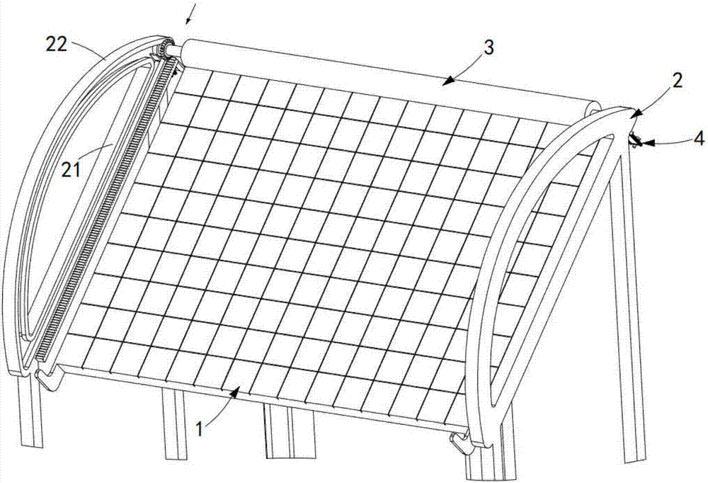
[0048] like figure 1 , figure 2 , image 3 and Figure 4 As shown, a limit mechanism for a photovoltaic power generation equipment cleaning device, including:

[0049] Photovoltaic power generation equipment 1, the photovoltaic power generation equipment 1 is set to rotate and swing;

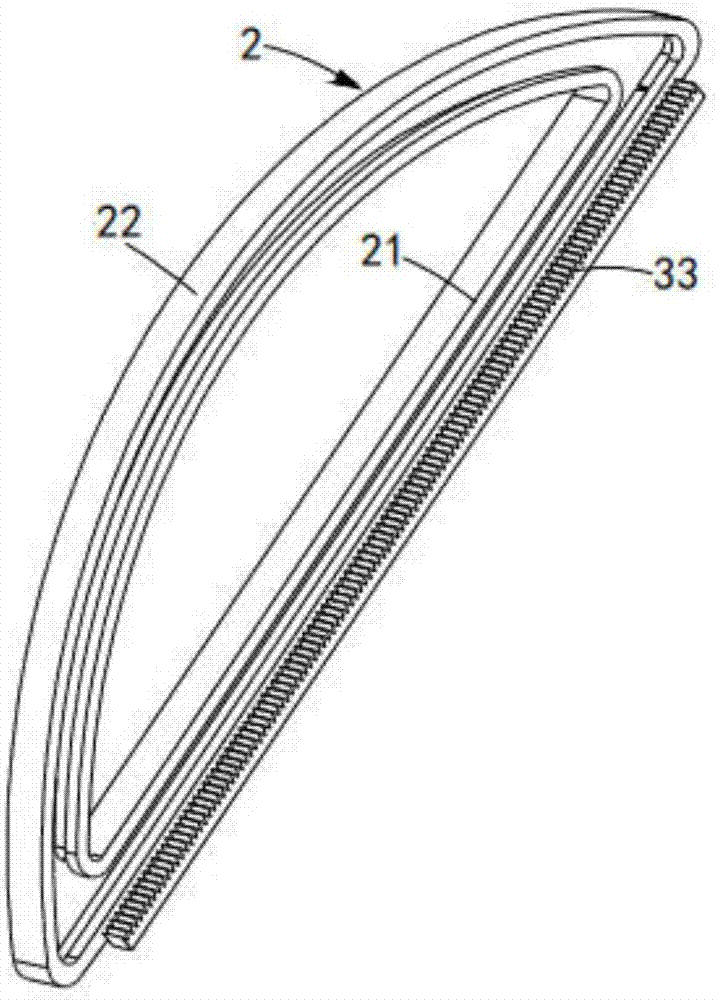
[0050] Guide rail 2, the guide rail 2 is symmetrically arranged on both sides of the photovoltaic power generation equipment 1, which includes a linear guide rail 21 and an arc guide rail 22, the linear guide rail 21 is arranged obliquely, and the arc guide rail 22 is connected to the linear guide rail both ends of 21;

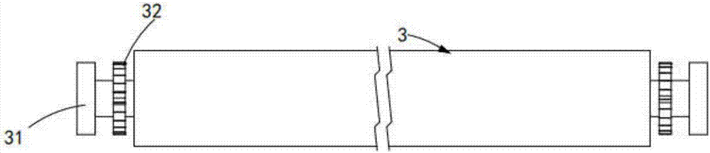
[0051] A cleaning roller 3, the cleaning roller 3 is rotatably arranged on the guide rail 2, and moves circularly along the guide rail 2;

[0052] The top of the linear guide rail 21 is provided with a limit mechanism 4, and the limit mechanism 4 includes:

[0053]The fixing assembly 41, the fixing assembly 41 is arranged on the top of the linear guide rail 21, and it lim...

Embodiment 2

[0075] Figure 8 It is a structural schematic diagram of Embodiment 2 of a limiting mechanism for a photovoltaic power generation equipment cleaning device of the present invention; Figure 8 As shown, the parts that are the same as or corresponding to the first embodiment adopt the corresponding reference numerals of the first embodiment. For the sake of simplicity, only the differences from the first embodiment will be described below. The second embodiment is similar to the first embodiment. figure 1 The difference of the shown embodiment one is:

[0076] Such as Figure 8 As shown, a limiting mechanism for a photovoltaic power generation equipment cleaning device, when the bottom of the second limiting plate 412 collides with the bottom of the guide post 413, the second limiting plate 412 and the first limiting plate The hinge point 412a of 411 is located at the inner sidewall of the bottom of the linear guide rail 21 , and at least one limiting member 411a is disposed o...


PUM


Abstract

The invention provides a limiting mechanism for a photovoltaic power generation equipment cleaning device. The limiting mechanism comprises photovoltaic power generation equipment which is arranged ina rotary swinging manner, guide rails which are symmetrically arranged on the two sides of the photovoltaic power generation equipment respectively and a cleaning roll which is rotationally arrangedon the guide rails; each guide rail comprises a linear guide rail and an arch-shaped guide rail; each linear guide rail is slantingly arranged; each arch-shaped guide rail is connected with the two ends of the corresponding linear guide rail; and limiting mechanisms, each of which comprises a fixing component and a lever component, are arranged on the tops of the linear guide rails respectively. The limiting mechanism provided by the invention has the beneficial effects that by utilizing locking of first limiting plates and the corresponding linear guide rails to limit the cleaning roll and through transmission matching between the lever components and the photovoltaic power generation equipment, locking between the first limiting plates and the corresponding linear guide rails is unlocked, the technical problem of limiting of the photovoltaic power generation equipment cleaning device is solved, regular release and limiting of the cleaning roll are realized, and the structure is novel.

Description

[0001] machine technology [0002] The invention relates to the technical field of mechanical structure of a photovoltaic power generation equipment cleaning device, in particular to a limiting mechanism for a photovoltaic power generation equipment cleaning device. Background technique [0003] Affected by the pollution problems in the world today, solar energy, as a clean and renewable energy source, has attracted more and more attention. It mainly includes three parts: solar panel components, controllers and inverters. The main components are electronic components. constitute. Solar cells can be packaged and protected after being connected in series to form a large-area solar cell module, and then combined with power controllers and other components to form photovoltaic power generation equipment. [0004] However, after the photovoltaic power generation equipment is placed in the wild, its surface is likely to be contaminated with a large amount of bird droppings, dust an...

Claims


Application Information

Patent Timeline
Patent Type & Authority Applications(China)
IPC IPC(8): B08B1/04B08B13/00H02S40/10
CPCB08B1/04B08B13/00H02S40/10Y02E10/50
Inventor 金丽丹
Owner 台州风达机器人科技有限公司
Why Eureka
Try Eureka