Pressure control system and pressure control method

A pressure control and pressure technology, applied in the pressure control system and control field, can solve the problems of small increase in pressure control range, unsatisfactory, cost increase, etc.

Inactive Publication Date: 2018-04-06
北京北方华创磁电科技有限公司
View PDF8 Cites 4 Cited by
  • Summary
  • Abstract
  • Description
  • Claims
  • Application Information

AI Technical Summary

Problems solved by technology

[0003] However, the method of increasing the intake air volume still has the following defects: 1) The increase in the pressure control range is small, which still cannot m

Method used


Image

  • Pressure control system and pressure control method
  • Pressure control system and pressure control method

Examples


Embodiment 1

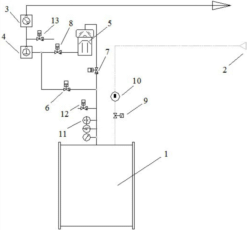
[0032] like figure 1 As shown, it is a pressure control system provided in this embodiment, including a vacuum chamber 1, a gas source 2, a vacuum pump group and a control unit; wherein, the vacuum chamber 1 communicates with the gas source 2 through an air intake pipeline, and the air intake pipeline is equipped with There is an air intake valve 9; the vacuum chamber 1 is connected to the vacuum pump group through the exhaust pipeline, and a high vacuum valve 7 is arranged on the exhaust pipeline; the air intake valve 9, the high vacuum valve 7 and the multi-stage vacuum pump group are respectively connected to the control unit; the control The unit controls the size of the pressure according to the target, and controls the pumping speed of the multi-stage vacuum pump group to realize the pressure regulation in the vacuum furnace.

[0033] In this embodiment, the gas source fills the vacuum chamber 1 with an inert gas; further, the inert gas is argon; the gas outlet of the mu...

Embodiment 2

[0046] This embodiment is basically the same as Embodiment 1. For the sake of brevity, in the description process of this embodiment, the same technical features as Embodiment 1 will not be described, and only the differences between this embodiment and Embodiment 1 will be described:

[0047] A flow meter 10 and a pressure meter 11 are also included. The flow meter 10 is arranged on the intake pipeline for controlling the intake air volume. The pressure gauge 11 is used to detect the pressure of the vacuum chamber 1 . The flow meter 10 and the pressure meter 11 are respectively connected to the control unit. In this embodiment, the opening degree of the flowmeter 10 is controlled by PID; the pressure gauge 11 is arranged on the connecting pipeline between the high vacuum valve 7 and the vacuum chamber 1 .

[0048] The following is a further detailed description through specific work projects.

[0049] After the adjustment of the vacuum pump unit is completed, the pumping c...

Embodiment 3

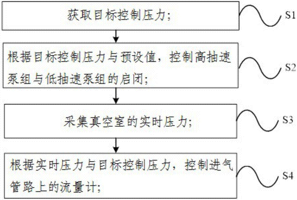
[0053] This embodiment provides a pressure control method, including the following steps:

[0054] S1. Obtain the target control pressure;

[0055] S2. According to the target control pressure and the preset value, control the opening and closing of the high pumping speed pump group and the low pumping speed pump group, as follows:

[0056] The intake valve 9 is opened, and the gas source 2 fills the vacuum chamber 1 with argon, and keeps the amount of intake constant.

[0057] If the target control pressure is lower than the preset value, the pre-pumping valve 6 is closed, and the high vacuum valve 7 and the backing valve 8 are opened. The first vacuum pump 3, the second vacuum pump 4 and the third vacuum pump 5 are running;

[0058] If the target control pressure is higher than the preset value, the high vacuum valve 7 and the front valve 8 are closed, the pre-pumping valve 6 is opened, the first vacuum pump 3 and the second vacuum pump 4 are opened, and the third vacuum p...


PUM


Abstract

The invention provides a pressure control system comprising a vacuum chamber, an air source, multiple grades of vacuum pump groups and a control unit. The vacuum chamber communicates with the air source through an intake pipeline. The intake pipeline is provided with an intake valve. The vacuum chamber communicates with the multiple grades of vacuum pump groups through an exhausting pipeline. A high vacuum valve is arranged on the exhaust pipeline. The intake valve, the high vacuum valve and the multiple grades of vacuum pump groups are connected with the control unit. The control unit controls the pumping speeds of the multiple grades of vacuum pump groups according to the target control pressure, so that pressure adjustment in a vacuum furnace is achieved. The invention provides a pressure control method. The pressure control method comprises the steps that the target control pressure is obtained; according to the target control pressure and a preset value, a high-pumping-speed pumpgroup and a low-pumping-speed pump group are controlled to started or stopped, if the target control pressure is higher than the preset value, the high-pumping-speed pump group is stopped, and the low-pumping-speed pump group is started, and if the target control pressure is lower than a preset value, the high-pumping-speed pump group and the low-pumping-speed pump group are both started. By the adoption of the pressure control system and the pressure control method, the change of the intake amount does not need to be changed, the cost is low, and the pressure control range is large.

Description

technical field [0001] The invention relates to the technical field of pressure control, in particular to a pressure control system and a control method. Background technique [0002] Due to the needs of the process in the vacuum heat treatment equipment, the pressure needs to be stably controlled at a certain stage. The current pressure control system can only achieve pressure stability control in a small range. In order to achieve a wider range of pressure control, the common solution is to increase the intake air volume. [0003] However, the method of increasing the intake air volume still has the following defects: 1) The increase in the pressure control range is small, which still cannot meet the current pressure control range requirements; 2) Since the intake air is generally inert gas, the intake air volume increases , leading to an increase in cost. Contents of the invention [0004] (1) Technical problems to be solved [0005] The present invention aims to so...

Claims


Application Information

Patent Timeline
IPC IPC(8): C21D1/773C21D11/00
CPCC21D1/773C21D11/00
Inventor 王青春张永军
Owner 北京北方华创磁电科技有限公司
Why Eureka
Try Eureka