Water mist dedusting device used for road dust

A dust removal device and dust technology, applied in the application field of sanitation engineering, can solve the problems of inconvenient operation, troublesome change of the inclination angle of the dust removal device, inability to adjust the spray angle of water mist at will, etc., and achieve the effect of compact connection and simple structure.

Inactive Publication Date: 2018-04-06
广西新主张城市管理服务有限公司
View PDF7 Cites 5 Cited by
  • Summary
  • Abstract
  • Description
  • Claims
  • Application Information

AI Technical Summary

Problems solved by technology

[0003] The existing water mist dedusting device still has certain defects in use. Although the existing dedusting device can spray high-pressure water mist to absorb dust and make the dust fall to the ground, the water mist of the fog gun machine is usually It is divergent, and the spray angle of the water mist cannot be adjusted at will, so it is not convenient to change the spray angle to achieve the effect of long-distance dust removal, and the existing dust removal device is troublesome to change the inclination angle, and it is not easy to operate

Method used


Image

  • Water mist dedusting device used for road dust
  • Water mist dedusting device used for road dust
  • Water mist dedusting device used for road dust

Examples


Embodiment 1

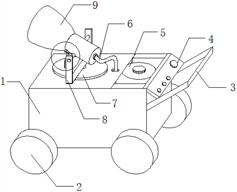
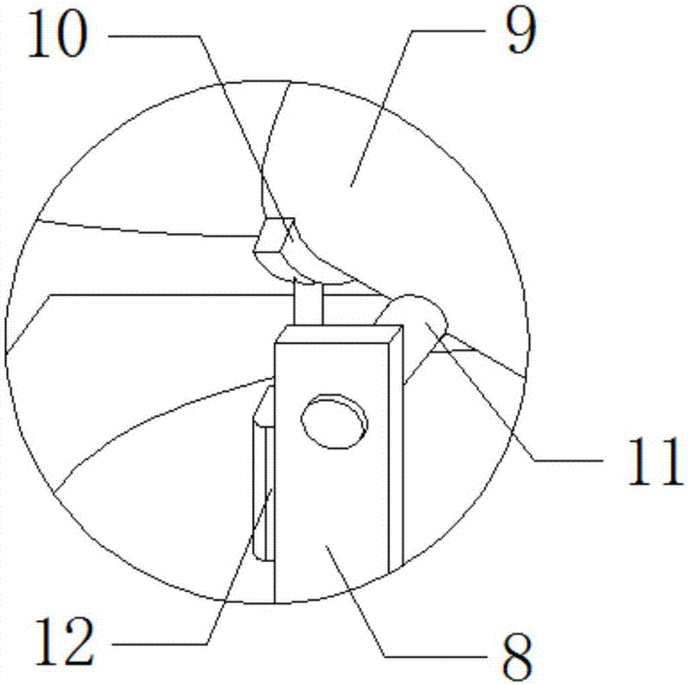
[0024] see Figure 1-5 As shown, a water mist dedusting device for road dust comprises a carriage 1, a water storage bucket 5 and a spray canister 9. Several rollers 2 are arranged at the bottom of the carriage 1, and an armrest 3 is arranged at one end of the carriage 1. Pushing the handrail 3 can make The compartment 1 moves around with the rollers 2 to facilitate the movement and transportation of the device. A control panel 4 is set on one side of the handrail 3, a water storage bucket 5 is set inside the compartment 1, a side of the water storage bucket 5 is set, and a motor 24 is set on the top of the motor. The bottom of 24 is provided with power supply block 25, and the top of motor 24 is equipped with turntable 7, and the top of turntable 7 is provided with support 8, and the top of support 8 is provided with turning bar 11, and the outer wall of turning bar 11 is socketed spray tube 9, and the bottom of spray tube 9 is installed Support block 10, the bottom of suppor...

Embodiment 2

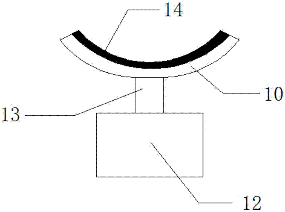
[0026] In addition, refer to Figure 1-5 , different from the above-mentioned embodiment 1, the turntable 7 and the motor 24 are connected in rotation, and the support 8 is connected to the turntable 7, so that the motor 24 provides sufficient rotational power for the turntable 7, thereby driving the spray canister on the support 8 9 rotates, one end of the spray tube 9 is provided with a funnel-shaped opening, and several baffles 22 are arranged in a funnel-shaped structure, so that the funnel-shaped opening of the spray tube 9 can facilitate the spraying of water mist from the nozzle 21, and the baffle 22 can surround the nozzle 21 The dispersed water mist is aggregated, the support block 10 is in an arc-shaped structure, and the support block 10 matches the specification of the slot at the bottom of the spray tube 9, so that the support block 10 can be stably attached to the bottom of the spray tube 9, and the The spray tube 9 and the support block 10 are easy to disassembl...


PUM


Abstract

The invention discloses a water mist dedusting device used for road dust. The water mist dedusting device comprises a compartment, rolling wheels, a handrail, a control panel, a water storage bucket,a water pipe, a rotating disc, a bracket, a spray cylinder, a supporting block, a rotating rod, a first hydraulic pump, a telescopic rod, a magnet sheet, a high-pressure water pump, a second hydraulicpump, a division plate, a piston rod, a hose, buffer boxes, nozzles, baffles, a spring, a motor and a power block. The water mist dedusting device used for the road dust has the beneficial effects that the bottom end of the spray cylinder is connected with the bracket through the rotating rod so that the spray cylinder can swing up and down, the supporting block controlled through the hydraulic pumps is mounted at the bottom of the spray cylinder, the magnet sheet is arranged on the top of the supporting block, and the specification of the magnet sheet is matched with the specification of a magnet sheet in a clamping groove in the bottom of the spray cylinder so that the supporting block can be connected into the bottom of the spray cylinder in a clamped mode, shaking of the spray cylinder during swing up and down is prevented, and steering of the spray cylinder can be conveniently controlled through the motor; and the water mist dedusting device used for the road dust has the characteristics that operation is convenient, and adjusting of the spraying distance is convenient.

Description

technical field [0001] The invention relates to a dust removal device, in particular to a water mist dust removal device for road dust, and belongs to the technical field of sanitation engineering applications. Background technique [0002] With the development of society, more and more vehicles are driving on the road. After the dust on the road has accumulated to a certain extent, the dust will be scattered when the vehicle is driving. Usually, the fog cannon machine is used to remove dust from the road. The fog cannon The machine is specially used for the source control of dust. Through the high-pressure nozzle, water mist with the same size as the dust is sprayed out. The water mist and dust are combined to form agglomerates, and the effect of sedimentation is achieved under the action of gravity. [0003] The existing water mist dedusting device still has certain defects in use. Although the existing dedusting device can spray high-pressure water mist to absorb dust and...

Claims


Application Information

Patent Timeline
Patent Type & Authority Applications(China)
IPC IPC(8): E01H3/02B01D47/06
CPCE01H3/02B01D47/06
Inventor 刘鸿宾郑富强
Owner 广西新主张城市管理服务有限公司
Why Eureka
Try Eureka