Water distribution device and water-consuming system with same

A water divider and water outlet technology, which is applied in branch pipelines, pipes, pipes/pipe joints/pipe fittings, etc., can solve the problems of increasing the difficulty of on-site installation and installation efficiency, and achieve stable and reliable product structure and easy assembly and connection. , the effect of stable diversion

Pending Publication Date: 2018-04-06
苏州众能医疗科技有限公司
View PDF0 Cites 1 Cited by
  • Summary
  • Abstract
  • Description
  • Claims
  • Application Information

AI Technical Summary

Problems solved by technology

Moreover, the different diversion water outlet holes on the existing water separator usually have different sizes of apertures, so the pipe diameters of the joints connected to different water outlet holes are thick and thin, and the models are various. In this way, the differential design of the diversion flow is realized. Increased difficulty and efficiency of on-site installation

Method used


Image

  • Water distribution device and water-consuming system with same
  • Water distribution device and water-consuming system with same
  • Water distribution device and water-consuming system with same

Examples


Embodiment 1

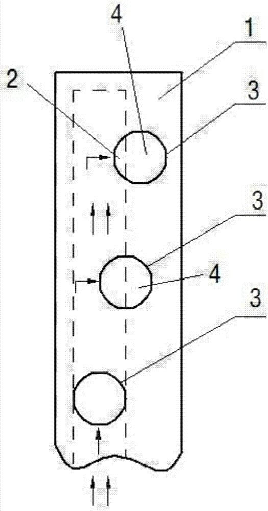
[0045] figure 1 A specific embodiment of the applicant's water separator is shown, which is the same as the traditional water separator in that it also includes a water separator housing 1, and a water inlet chamber is formed in the water separator housing 1 2. The outer surface of the water distributor housing 1 is provided with a plurality of ( figure 1 Only 3) water outlet holes 3 are shown in . Obviously, the water outlet hole 3 has an outer end far away from the water inlet chamber 2 and an inner end close to the water inlet chamber 2 .

[0046] The key improvement of this embodiment is that the above-mentioned three water outlet holes 3 all have the same hole type and diameter, and the inner ends of the two water outlet holes 3 are provided with a water retaining member 4 that partially blocks the water outlet section of the water outlet holes .

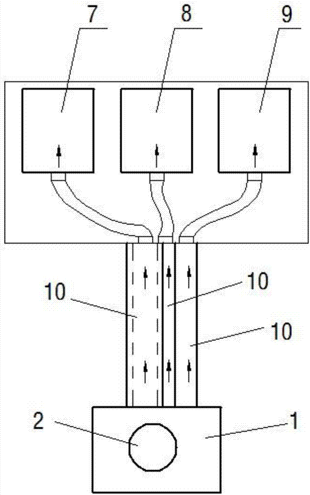
[0047] figure 2 It shows a specific application example of this kind of water divider in a certain water system. In the ...

Embodiment 2

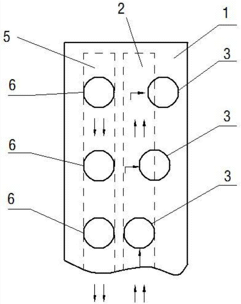
[0055] image 3 Shows the second specific embodiment of the applicant's water separator, Figure 4 A specific application example of the water separator of this embodiment in another water system is shown.

[0056] The structure of the water separator in this embodiment is basically the same as that of the above-mentioned embodiment 1, the difference is that: the water inlet chamber 2 is also formed in the water separator housing 1 and the water return chamber 5 is isolated from each other, and the water separator housing 1 offers three backwater holes 6 communicating with the aforementioned backwater chamber 5 . And the aforementioned water return hole 5 also has the same hole shape and hole diameter as the three water outlet holes 3 . In this way, the water diversion joint connected to the water return hole 5 and the water diversion joint connected to the water outlet hole 3 can adopt exactly the same specifications.

[0057] refer to Figure 4 As shown, the three water ...

Embodiment 3

[0060] Figure 5 A third specific embodiment of the applicant's water separator is shown, Figure 6 A specific application example of the water separator of this embodiment in the third water system is shown.

[0061] The structure of the water distributor in this embodiment is basically the same as that of the second embodiment above, the difference is that the water retaining member 4 adopts a completely different structural form, specifically: the water retaining member 4 arranged at the inner end of the water outlet hole 3 is a set The baffle plate structure of a plurality of small holes, the outer contour of this baffle plate completely blocks the water outlet cross-section at the inner side of the water outlet hole 3, and only leaves the small holes provided on it for water flow to flow out. Those water retaining members 4 with a large number of small holes and a large total area of ​​the small holes have larger water outlet flow rates of the corresponding water outlet ...


PUM


Abstract

The invention discloses a water distribution device and a water-consuming system with the same. The water distribution device comprises a water distribution device shell, a water inlet chamber formedin the water distribution device shell and at least two water outlet holes which are formed in the water distribution device shell and communicate with the water inlet chamber, and each water outlet hole is provided with an outer side end far away from the water inlet chamber and an inner side end close to the water inlet chamber. The water outlet holes are the same in hole type and hole diameter.The inner side end of at least one water outlet hole is provided with a water blocking piece for blocking part of a water outlet cross section of the water outlet hole. According to the water distribution device, different shunting flows can also be achieved under the situation that no flow control valve is arranged even though all water guide connectors in the same specification are connected with the water distribution water outlet holes, and the using process is very convenient.

Description

technical field [0001] The present application relates to a water separator and a water system equipped with the water separator. Background technique [0002] The water separator is a water distribution and collection device used to connect the water supply and return water of various heating pipes in the water system. According to the inlet and outlet water, it is divided into water separator and water collector. Therefore, it is called a water separator or a water collector, commonly known as a water separator. The water separator used in the floor heating and air conditioning system should be made of brass, and the water separator used in the renovation of the household surface of the tap water supply system is mostly made of PP or PE. Both supply and return water are equipped with exhaust valves, and many water separators are also equipped with drain valves for supply and return water. Valves should be installed in each branch of the water supply pipe to adjust the w...

Claims


Application Information

Patent Timeline
IPC IPC(8): F16L41/03
CPCF16L41/03
Inventor 陈启兴周伟绩
Owner 苏州众能医疗科技有限公司
Why Eureka
Try Eureka