Monitoring system and method

A monitoring system and one-to-one correspondence technology, applied in the field of data processing, can solve problems such as water pollution, blockage, and sludge accumulation

Inactive Publication Date: 2018-04-06
成都声立德克技术有限公司
View PDF10 Cites 0 Cited by
  • Summary
  • Abstract
  • Description
  • Claims
  • Application Information

AI Technical Summary

Problems solved by technology

[0003] In view of this, the purpose of the embodiment of the present invention is to provide a monitoring system and method to alleviate the need to install valves to form a physical DMA area when monitoring the leakage of the water supply pipe network, which will cause stagnant water to cause water quality pollution, and will also The problem of sludge accumulation or even clogging

Method used


Image

  • Monitoring system and method
  • Monitoring system and method
  • Monitoring system and method

Examples


no. 1 example

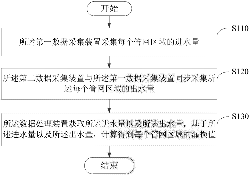
[0032] Please refer to image 3 , image 3 It is a flowchart of a monitoring method provided by the first embodiment of the present invention, and the method is applied to a monitoring system for monitoring a water supply pipe network. The water supply pipe network includes at least one pipe network area, which can be regarded as a virtual DMA area formed by placing data acquisition devices. It is worth pointing out that this virtual bordered DMA area only needs to install data acquisition devices The device can be formed without installing physical valves.

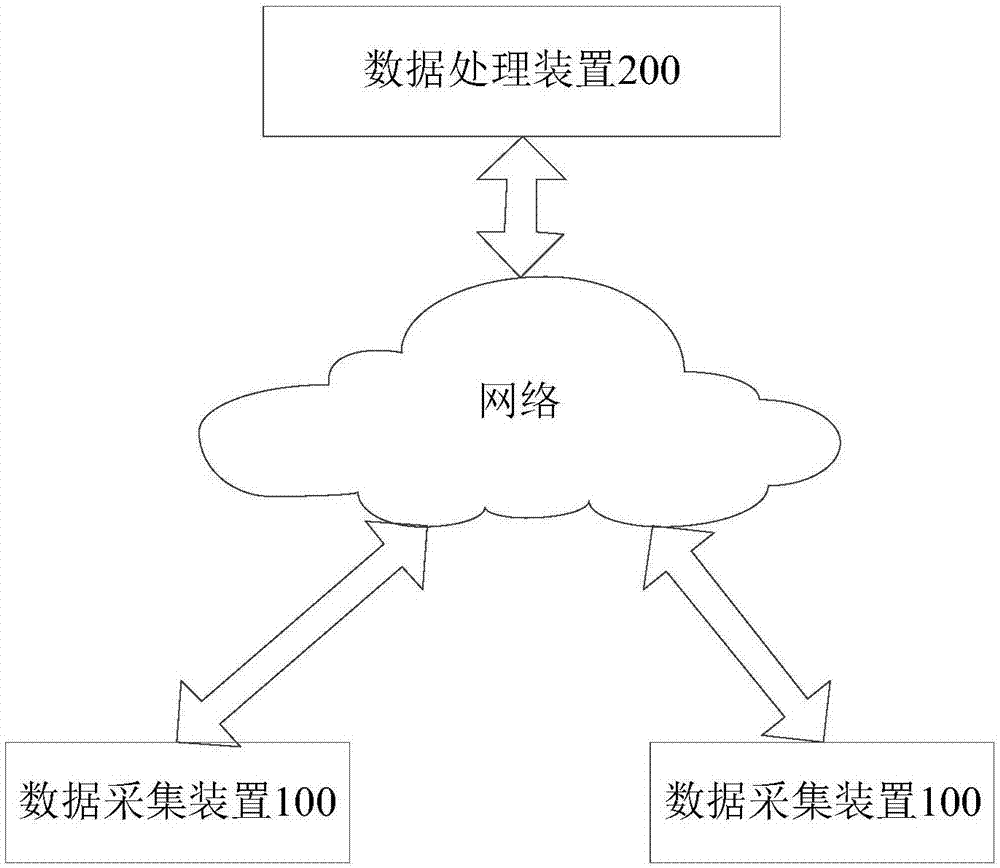
[0033] Wherein, the system includes: a data processing device, a first data acquisition device arranged at the water inlet of each pipe network area in the at least one pipe network area, a second data collection device arranged at the water outlet of each pipe network area A data collection device, the data processing device is respectively connected in communication with the first data collection device and the second...

no. 2 example

[0046] Please refer to Figure 5 , Figure 5 It is a structural block diagram of a monitoring system 10 provided by the second embodiment of the present invention. The monitoring system 10 is applied in the water supply pipe network, and the water supply pipe network includes at least one pipe network area, which will be described below Figure 5 The shown structural block diagram is described, and the monitoring system 10 shown includes: a first data acquisition device 101 arranged at the water inlet of each pipe network area in the at least one pipe network area, a first data acquisition device 101 arranged at each pipe network area The second data collection device 102 and the data processing device 200 at the water outlet, the data processing device 200 is in communication connection with the first data collection device 101 and the second data collection device 102 respectively.

[0047] The first data collection device 101 is used to collect the water intake of each pi...


PUM


Abstract

The invention provides a monitoring system and a method. The monitoring system includes a data treatment device, a first data collecting device and a second data collecting device, wherein, a first data collecting device is arranged at a water-in-position of every pipe network regions of at least one pipe network region, a second data collecting device is arranged at a water-out-position of everypipe network regions, and the data treatment device is separately connected with the first data collecting device and the second data collecting device in a communicating mode; the first data collecting device is used for collecting water inflow of every pipe network regions; the second data collecting device is used for collecting water flow of every pipe network regions in synchronization with the first data collecting device; and the data treatment device is used for calculating water inflow and water flow to acquire leakage values of every pipe network regions. The monitoring system and the method can relief the problems that when leakage of the present water-supplying pipe networks is monitored, a valve is installed to form an entity DMA region, water is polluted, and sludge is accumulated and even blocks the pipe networks.

Description

technical field [0001] The present invention relates to the field of data processing, in particular to a monitoring system and method. Background technique [0002] The leakage rate of my country's current water supply pipe network is still hovering around 30%, and the leakage of the pipe network has caused a huge waste of water resources. As the government strengthens the construction of social water supply management, it puts forward requirements for the basic leakage rate of the pipe network of urban water supply enterprises in my country. In order to achieve the ambitious goal of a leakage rate of less than 12%, the widely used or recommended pipeline network leakage detection technology is the DMA metering and partitioning technology. This technology requires it to divide the urban pipe network into many small, manageable water supply areas according to certain rules, and to install valves on the boundaries of each area so as to make it independent of its adjacent wate...

Claims


Application Information

Patent Timeline
Patent Type & Authority Applications(China)
IPC IPC(8): F17D5/02
CPCF17D5/02
Inventor 沈畅陈仲阳陈明
Owner 成都声立德克技术有限公司
Why Eureka
Try Eureka