Variable-frequency aeration device for rare earth tail water treatment

An aeration device and frequency conversion technology, applied in the field of frequency conversion aeration, can solve the problems of reduced processing efficiency

Inactive Publication Date: 2021-02-26
江西挺进环保科技股份有限公司
View PDF0 Cites 0 Cited by
  • Summary
  • Abstract
  • Description
  • Claims
  • Application Information

AI Technical Summary

Problems solved by technology

In order to ensure that the microorganisms in the pool can oxidize and decompose the organic matter in the sewage under the condition of sufficient dissolved oxygen, the overall processing efficiency is reduced due to the lack of aeration

Method used


Image

  • Variable-frequency aeration device for rare earth tail water treatment
  • Variable-frequency aeration device for rare earth tail water treatment
  • Variable-frequency aeration device for rare earth tail water treatment

Examples


Embodiment 1

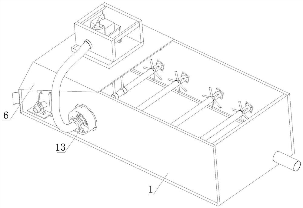
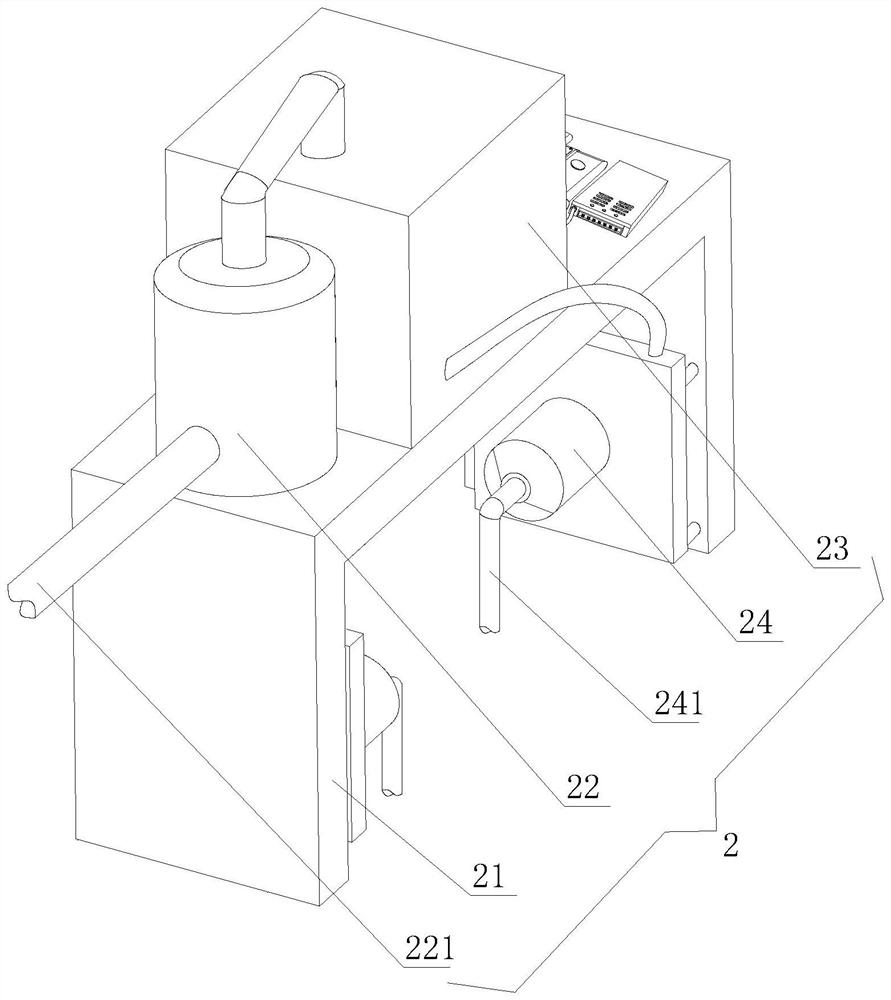
[0030] see figure 1 , a frequency conversion type aeration device for rare earth tail water treatment, comprising an aeration tank 1, a power mechanism 2, a stirring mechanism 3 and a frequency conversion mechanism 4, the top of the aeration tank 1 is covered with an upper cover 6, and the upper cover 6 aerates The top part of the tank 1 is covered, the power mechanism 2 and the frequency conversion mechanism 4 are connected and installed on the top surface of the upper cover 6, the power mechanism 2 and the frequency conversion mechanism 4 are arranged side by side, and the stirring mechanism 3 is distributed inside the aeration tank 1 , the stirring mechanism 3 works in the aeration tank 1 to stir the liquid in the aeration tank 1, and one end of the power mechanism 2 is set on the stirring mechanism 3, and a large amount of gas generated by the power mechanism 2 is discharged from the stirring mechanism 3, so as to realize stirring while stirring purpose of aeration.

[00...

Embodiment 2

[0040] see figure 1 , the top of the aeration tank 1 is covered with an upper cover 6, the upper cover 6 covers a part of the top of the aeration tank 1, the power mechanism 2 and the frequency conversion mechanism 4 are connected and installed on the top surface of the upper cover 6, the power mechanism 2 It is arranged side by side with the frequency conversion mechanism 4. The stirring mechanism 3 is distributed inside the aeration tank 1. The stirring mechanism 3 works in the aeration tank 1 to stir the liquid in the aeration tank 1. One end of the power mechanism 2 is set on the stirring mechanism 3. A large amount of gas generated by the power mechanism 2 is discharged from the stirring mechanism 3, thereby achieving the purpose of aeration while stirring.

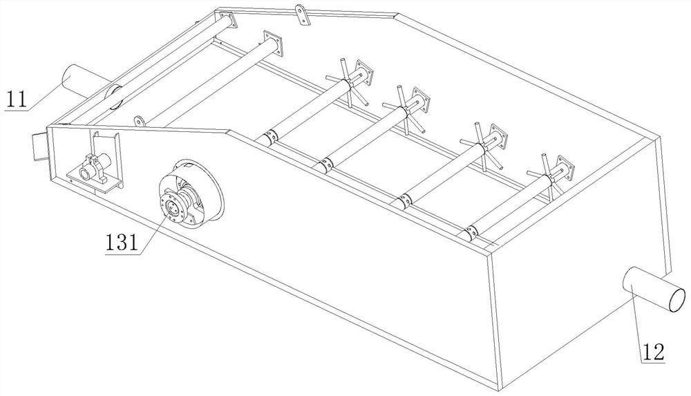
[0041] see figure 2 A liquid inlet pipe 11 and a liquid outlet pipe 12 are installed on both sides of the front and back of the aeration tank 1, and a water valve is installed on the liquid inlet pipe 11 and the li...


PUM


Abstract

The invention discloses a variable-frequency aeration device for rare earth tail water treatment, which belongs to the technical field of variable-frequency aeration and comprises an aeration tank, apower mechanism, a stirring mechanism and a variable-frequency mechanism, the top of the aeration tank is covered with an upper cover, the power mechanism and the variable-frequency mechanism are connected and mounted on the top surface of the upper cover, and the stirring mechanism is distributed inside the aeration tank. And one end of the power mechanism sleeves the stirring mechanism. According to the variable-frequency aeration device for rare earth tail water treatment, a main pipe of an air pump sleeves a rotating shaft, air extracted by the air pump is fed into the rotating shaft through the main pipe, a stirring shaft rotates around the rotating shaft, and in the rotating process, the connecting position of the two parts is connected through a sealing ring, so that the problem ofpoor sealing performance cannot occur; gas conveyed by the air pump can completely enter the rotating shaft, the main pipe is communicated with an inner cavity of the stirring shaft, an auxiliary pressurizing pipe conveys the gas to the stirring shaft through air holes, finally an aeration disc aerates the gas, the flow speed of the gas conveyed into the stirring mechanism is changed, and frequency conversion is achieved.

Description

technical field [0001] The invention relates to the technical field of frequency conversion aeration, in particular to a frequency conversion aeration device for rare earth tail water treatment. Background technique [0002] The source of rare earth mine tail water is two aspects: on the one hand, it comes from the tail water after clear water washing of rare earth mines. Clean water cleaning is mainly aimed at the fact that the soil in the in-situ leaching stope still contains ammonia nitrogen, which has potential environmental risks. The mine is required to fill in clean water for cleaning, and then use the liquid collection system in the in-situ leaching stope to collect tail water; on the other hand , derived from the seepage fluid produced by leaching under natural rainfall conditions after the mining of rare earth mines. The tail water of rare earth mines contains ammonia nitrogen, sulfate and rare earth ions with low concentration. The rare earth ions in the tail wat...

Claims


Application Information

Patent Timeline
Patent Type & Authority Applications(China)
IPC IPC(8): C02F7/00C02F103/10
CPCC02F7/00C02F2103/10Y02W10/10
Inventor 宁小飞简陈生马密林王鹏宗毅
Owner 江西挺进环保科技股份有限公司
Why Eureka
Try Eureka