
Refrigerant circulating system and control method thereof

A refrigerant circulation system and refrigerant technology, which are applied in the direction of fluid circulation arrangement, compressors with reversible circulation, refrigerators, etc., can solve the problems affecting the operation stability of the refrigerant circulation system and the long defrosting time, so as to ensure the defrosting efficiency. , Improve the utilization rate and ensure the effect of comfort

Pending Publication Date: 2018-04-06
GREE ELECTRIC APPLIANCES INC
View PDF7 Cites 6 Cited by
  • Summary
  • Abstract
  • Description
  • Claims
  • Application Information

AI Technical Summary

Problems solved by technology

[0003] In the existing refrigerant circulation system that utilizes the heat storage of heat storage materials for defrosting, when the system is defrosting, the system still operates in heating mode, and the heat accumulator with heat storage materials and the outdoor heat exchanger form a refrigerant cycle The indoor heat exchanger and the outdoor heat exchanger form a refrigerant circulation loop. Therefore, at this stage, the heat accumulator serves as a heat source to supply heat to the indoor heat exchanger and the outdoor heat exchanger at the same time, and heat is exchanged in the indoor heat exchanger. The remaining refrigerant will still flow into the outdoor heat exchanger, resulting in a long defrosting time and affecting the operation stability of the refrigerant circulation system

Method used


Image

  • Refrigerant circulating system and control method thereof
  • Refrigerant circulating system and control method thereof
  • Refrigerant circulating system and control method thereof

Examples


Embodiment Construction

[0073] The present invention is described below based on examples, but the present invention is not limited to these examples. In the following detailed description of the invention, some specific details are set forth in detail. The present invention can be fully understood by those skilled in the art without the description of these detailed parts. To avoid obscuring the essence of the present invention, well-known methods, procedures, procedures, and components have not been described in detail.

[0074] Additionally, those of ordinary skill in the art will appreciate that the drawings provided herein are for illustrative purposes and are not necessarily drawn to scale.

[0075] Unless the context clearly requires, throughout the specification and claims, "comprises", "comprises" and similar words should be interpreted in an inclusive sense rather than an exclusive or exhaustive meaning; that is, "including but not limited to" meaning.

[0076] In the description of the ...


PUM

PropertyMeasurementUnit
Phase transition temperatureaaaaaaaaaa

Abstract

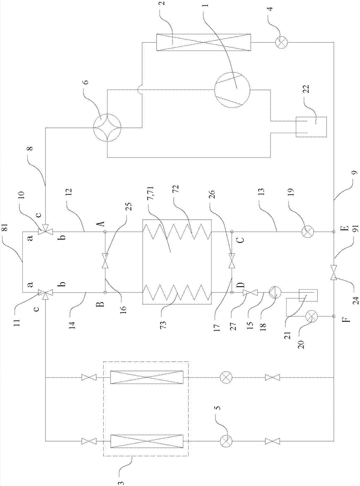
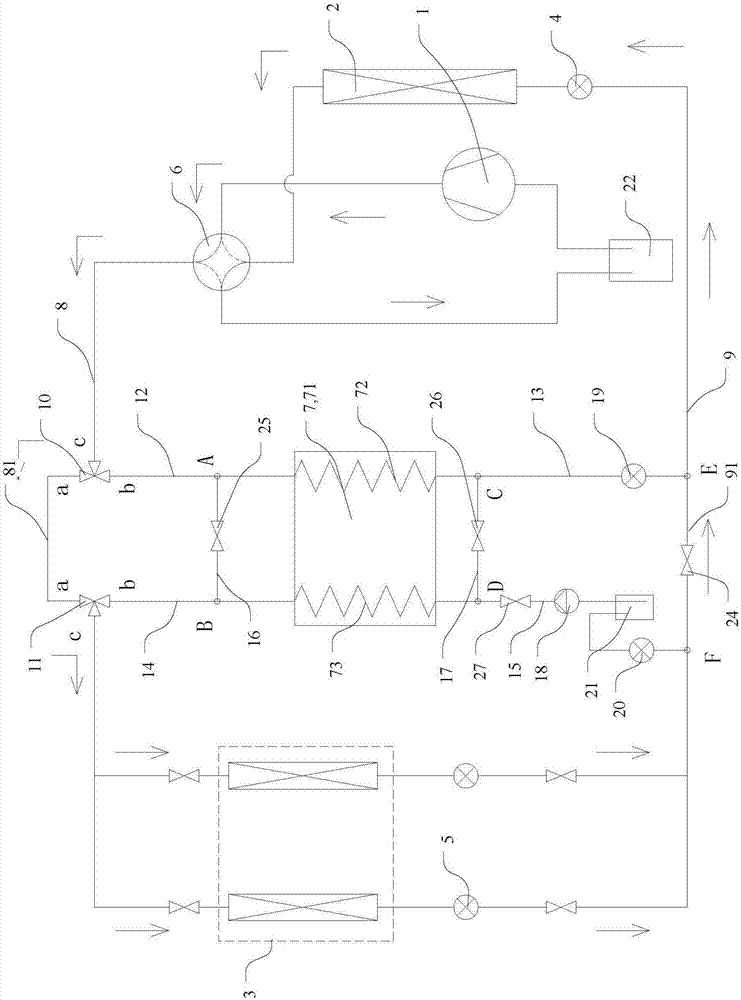
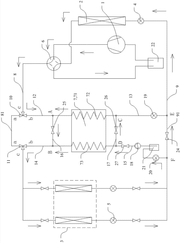
The invention discloses a refrigerant circulating system and a control method thereof. The refrigerant circulating system comprises a compressor, an outdoor heat exchange part, an indoor heat exchangepart and a throttling device which are connected through pipelines. The pipelines comprise the first pipeline connected with an exhaust port of the compressor and a heating operation refrigerant inlet of the indoor heat exchange part, and the second pipeline connected with a heating operation refrigerant outlet of the indoor heat exchange part and a heating operation refrigerant inlet of the outdoor heat exchange part; the refrigerant circulating system further comprises an energy storage module; the energy storage module comprises a heat / cold storage part, a first heat exchange flow path anda second heat exchange flow path, wherein the first heat exchange flow path and the second heat exchange flow path can exchange heat with the heat / cold storage part; the first ends of the first heatexchange flow path and the second heat exchange flow path are both connected with the first pipeline, and the second ends of the first heat exchange flow path and the second heat exchange flow path are both connected with the second pipeline; and the two ends of the two heat exchange flow paths are connected into a main refrigerant pipeline of the refrigerant circulating system so that the two heat exchange flow paths can participate in refrigerant circulation independently.

Description

technical field [0001] The invention relates to the technical field of refrigeration and heating systems, in particular to a refrigerant circulation system and a control method thereof. Background technique [0002] When the heat pump system or air conditioning system is running in the heating mode, especially when the outdoor temperature is low and the humidity is high, the outdoor heat exchanger is prone to frost, which seriously affects the performance of the heat exchanger. At present, the commonly used defrosting methods include reverse cycle defrosting, hot gas bypass defrosting and thermal storage defrosting. During reverse cycle defrosting, the system is a refrigeration cycle, and no heat is supplied to the room during defrosting; when hot gas bypasses defrosting, it can only be defrosted through the heat supplied by the compressor, so the defrosting time is relatively long, and the frost is not easy to clean . These two defrosting methods will cause indoor tempera...

Claims


Application Information

Patent Timeline
IPC IPC(8): F25B13/00F25B47/02F25B49/02F25B41/04F28D20/02F25B41/20
CPCF25B13/00F25B47/025F25B49/02F28D20/02F25B2313/029F25B2400/24F25B41/20Y02E60/14
Inventor 杨瑞琦郑波梁祥飞
Owner GREE ELECTRIC APPLIANCES INC
Features
  • Generate Ideas
  • Intellectual Property
  • Life Sciences
  • Materials
  • Tech Scout
  • Unparalleled Data Quality
  • Higher Quality Content
  • 60% Fewer Hallucinations
Learn More