Conveying device of roller hearth furnace

A conveying device and roller hearth furnace technology, applied in the metallurgical field, can solve problems such as easy damage, damage to rollers and transmission mechanisms, large spacing, etc., and achieve the effects of high cost performance, novel structure, and high market promotion value.

Pending Publication Date: 2018-04-06
CERI PHOENIX INDAL FURNACE CO TD +1
View PDF0 Cites 3 Cited by
  • Summary
  • Abstract
  • Description
  • Claims
  • Application Information

AI Technical Summary

Problems solved by technology

[0004] The invention provides a conveying device for a roller hearth furnace to solve the problem that the distance between the inner roll

Method used


Image

  • Conveying device of roller hearth furnace

Examples


Embodiment Construction

[0025] In order to have a clearer understanding of the technical features, purposes and effects of the present invention, the present invention will now be described with reference to the accompanying drawings.

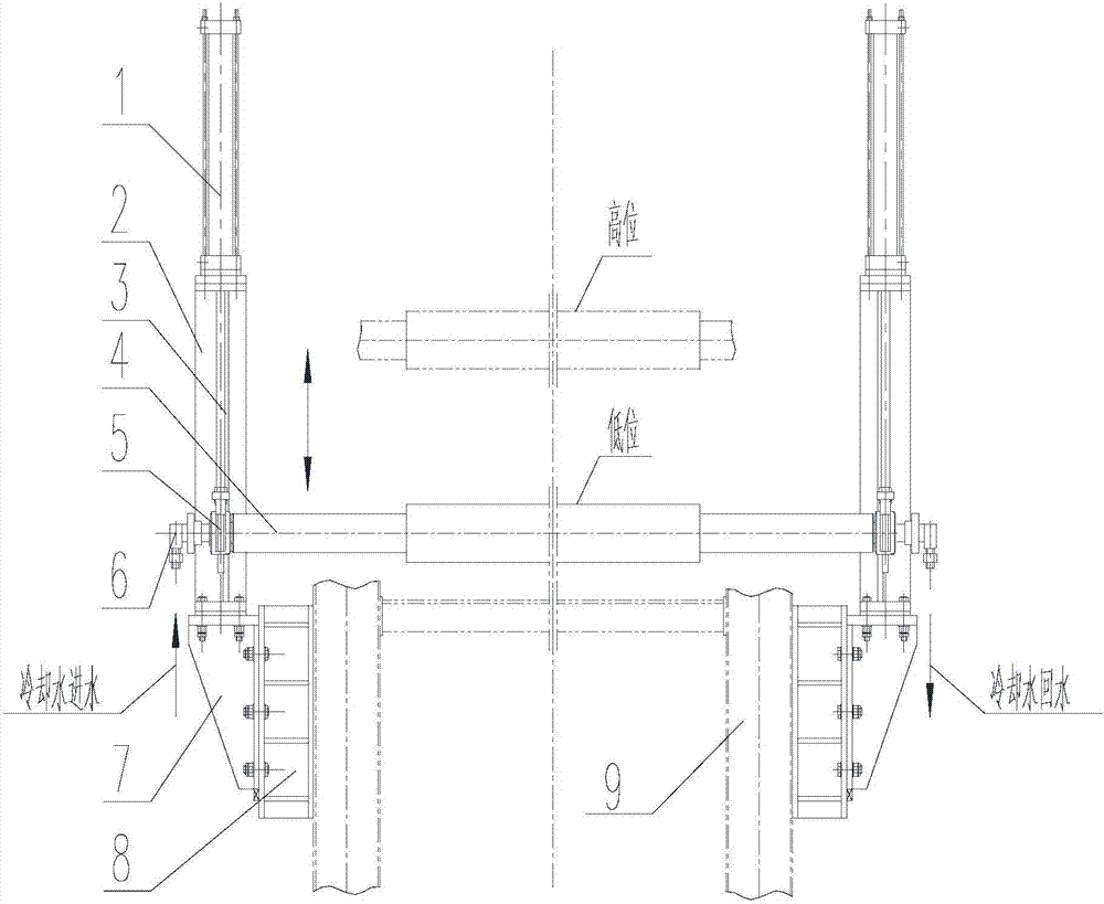
[0026] Such as figure 1 As shown, the present invention proposes a conveying device for a roller hearth furnace, which is used for the smooth conveyance of workpieces, and is installed between the inner roller and the outer roller of the roller hearth furnace to connect the inner and outer rollers of the furnace. The bottom of the roller hearth furnace is provided with an inner roller and an outer roller, and the conveying device of the roller hearth furnace includes:

[0027] Support 2, arranged outside the furnace of the roller hearth furnace;

[0028] The guide rail 3 is vertically arranged on the support 2;

[0029] The supporting roller 4 is arranged outside the furnace of the roller hearth furnace and is positioned between the inner roller and the outer roller...


PUM


Abstract

The invention provides a conveying device of a roller hearth furnace. A furnace inner roller and a furnace outer roller are arranged at the bottom of the roller bottom furnace. The conveying device ofthe roller hearth furnace comprises a bracket, a guide rail, a supporting roller, and a driving roller, wherein the bracket is arranged outside the furnace of the roller hearth furnace. The guide rail is vertically arranged on the bracket, the supporting roller is arranged outside the furnace of the roller hearth furnace and is disposed between an inner furnace roller and an outer furnace roller,the supporting roller can move up and down on the guide rail, the supporting roller is provided with a rotating shaft, the axial direction of the rotating shaft is disposed in the horizontal direction, and the axial direction of the rotating shaft is perpendicular to the moving direction of workpieces, and the workpieces are output from the roller bottom furnace. The driving device is connected with and drives the carrier roller. The device is novel in structure and ultra-high in cost performance, and overcomes the defects of a former roller hearth furnace and has extremely high market popularization value.

Description

technical field [0001] The invention relates to the field of metallurgy, in particular to a steel-moving mechanism in front of a kiln in a steel plant, in particular to a steel-moving mechanism between a billet conveying platform and a conveying roller table in the metallurgical industry, that is, a conveying device for a roller hearth furnace. Background technique [0002] In the metallurgical and machinery industry, due to the structural limitations of the furnace door lifting and pressing device, the distance between the furnace inner rollers located inside the furnace door and the furnace outer rollers outside the furnace door is relatively large. In the production of roller hearth furnace, the phenomenon of workpiece tilting or drooping often occurs. The larger the distance between the roller tables, the easier it is for the workpiece to impact the roller table during operation, resulting in damage to the rollers and the transmission mechanism. [0003] To sum up, the f...

Claims


Application Information

Patent Timeline
IPC IPC(8): F27D3/02F27D9/00
CPCF27D3/026F27D3/028F27D9/00F27D2009/0013F27D2009/0018
Inventor 郝冬宁成建民张晓龙
Owner CERI PHOENIX INDAL FURNACE CO TD
Why Eureka
Try Eureka