Method for testing performance of phase transition heat accumulation unit
A technology of phase change heat storage and testing method, applied in the direction of material thermal development, etc., can solve the problems of lower heat storage density, no consideration of phase change heat transfer characteristics, weight increase, etc., to achieve the effect of convenient operation
- Summary
- Abstract
- Description
- Claims
- Application Information
AI Technical Summary
Problems solved by technology
Method used
Image
Examples
Embodiment 1
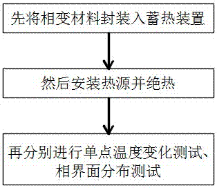
[0030] A performance test method for a phase change heat storage device, using a performance test system for a phase change heat storage device to test the performance of the heat storage device 11 .
[0031] Such as Figure 5 As shown, the performance testing system of the phase change thermal storage device 11 includes a box body surrounded by a plurality of heat preservation boards 8 to form a rectangular inner cavity, and a PID temperature control system and a temperature measurement system respectively installed on the box body. The temperature control system includes a heating plate 1 connected by a signal line, an AC contactor 2, a temperature control instrument 3, and a temperature sensing probe 4. The temperature control instrument 3 installed outside the box is connected to a vertical panel in the inner cavity The heating plate 1 on the straight wall, the output end of the temperature sensing probe 4 used to monitor the temperature of the heating plate 1 is connected...
Embodiment 2
[0047] In this embodiment, the heat storage device 11 with a rectangular cavity is taken as an example. The inner chamber of the performance testing device is exactly equivalent to the outer contour of the rectangular cavity heat storage device 11 to be performance tested.
[0048] Such as Figure 5 As shown, the rectangular cavity heat storage device 11 and the left side wall of the box are provided with a heating plate 1 as the sole heat source. At this time, the heating plate 1 is a rectangular plate and just coincides with the left side wall of the box body.
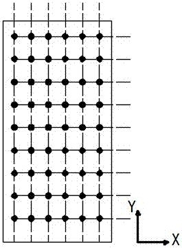
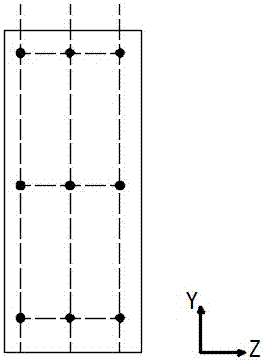
[0049] Such as figure 2 , image 3 As shown, take the width direction of the rectangular cavity heat storage device 11 as the X axis, the height direction of the rectangular cavity heat storage device 11 as the Y axis, and the length direction of the rectangular cavity heat storage device 11 as the Z axis. The origin in the figure represents the distribution position of the thermocouple 5, that is, the temperatu...
Embodiment 3
[0052] A method for testing the performance of a phase-change heat storage device. The heat storage device 11 is placed in the inner cavity, which includes a box body surrounded by a plurality of insulation boards 8 to form a rectangular inner cavity, and a PID temperature control system and a measurement system respectively installed on the box body. temperature system, the PID temperature control system includes a heating plate 1 connected by a signal line, an AC contactor 2, a temperature control instrument 3, and a temperature sensing probe 4, and the temperature control instrument 3 installed outside the box is connected by an AC contactor 2 The heating plate 1 is arranged on a vertical wall of the inner cavity, the output end of the temperature sensing probe 4 used to monitor the temperature of the heating plate 1 is connected to the temperature control instrument 3, and the input end of the temperature measurement system is fixed on the heat preservation plate 8 And it i...
PUM
 Abstract
Description
Claims
Application Information
 - R&D
- Intellectual Property
- Life Sciences
- Materials
- Tech Scout
- Unparalleled Data Quality
- Higher Quality Content
- 60% Fewer Hallucinations
Browse by: Latest US Patents, China's latest patents, Technical Efficacy Thesaurus, Application Domain, Technology Topic, Popular Technical Reports.
© 2025 PatSnap. All rights reserved.Legal|Privacy policy|Modern Slavery Act Transparency Statement|Sitemap|About US| Contact US: help@patsnap.com


