Multi-ring all-fiber current transformer

A current transformer, all-fiber technology, used in voltage/current isolation, measuring current/voltage, instruments, etc., can solve the problem of the large size of the current transformer sensing ring, the inability to achieve differential current measurement, and the difficulty in manufacturing process guarantees, etc. problems, to achieve the effect of improving protection reliability, improving system reliability, and reducing system cost and complexity

Inactive Publication Date: 2018-04-06
NR ELECTRIC CO LTD +1
View PDF6 Cites 2 Cited by
  • Summary
  • Abstract
  • Description
  • Claims
  • Application Information

AI Technical Summary

Problems solved by technology

Such a configuration scheme only needs one all-fiber-optic current transformer to realize the measurement of the combined current of each measuring point, which avoids the influence caused by the performance difference of each measuring point separately configured current transformer; The distance, size, and polarity of the current conductors have strict requirements. For example, some measuring po

Method used


Image

  • Multi-ring all-fiber current transformer
  • Multi-ring all-fiber current transformer
  • Multi-ring all-fiber current transformer

Examples


Example Embodiment

[0042] Embodiment one:

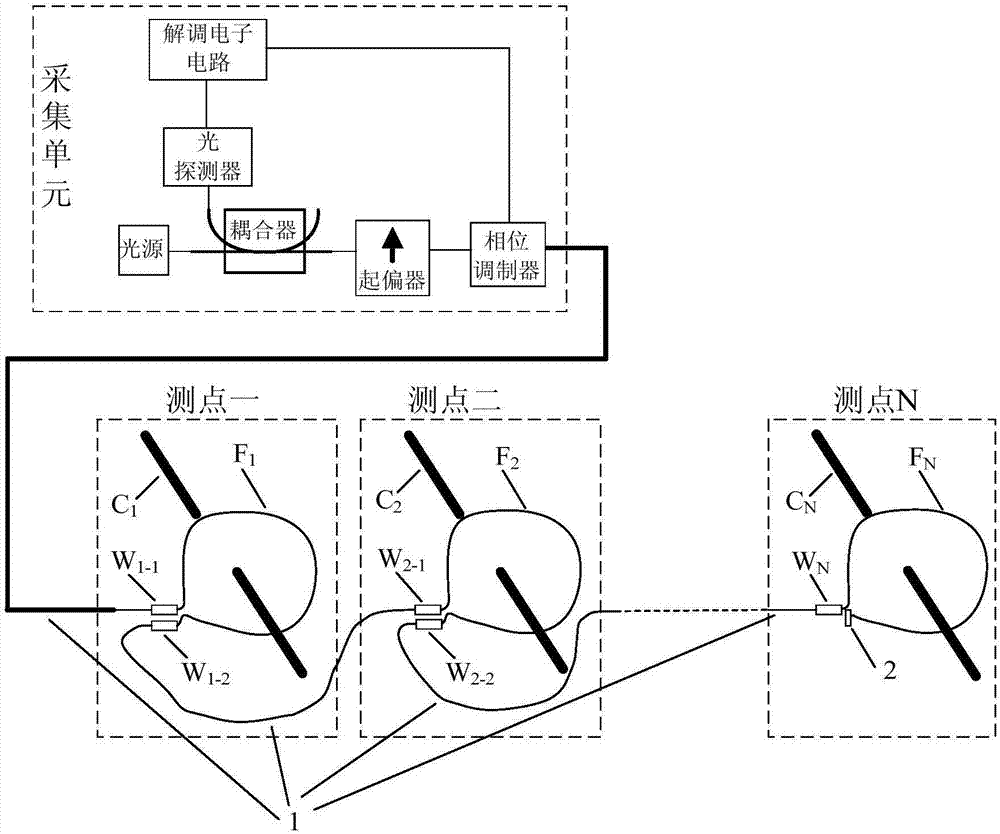
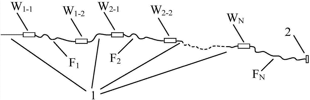
[0043] like Figure 5 As shown, it is a set of multi-ring optical CT for measuring line differential current. The multi-ring optical CT includes two sensing optical fiber rings, which are respectively wound on C 1 and C 2 On the conductor, the two optical fiber rings are connected through a polarization maintaining optical fiber 1 . The first optical fiber sensing loop of this optical CT consists of a λ / 4 wave plate W 1-1 , Sensing fiber F 1 and λ / 4 waveplate W 1-2 Composed of; the second optical fiber sensing loop consists of a λ / 4 wave plate W 2 , Sensing fiber F 2 and reflector 2. The winding directions of the sensing fibers of the two sensing fiber rings are opposite, so they exhibit positive and negative polarities respectively. Let the primary current value in the first optical fiber ring be I 1 , the phase shift caused by this current is φ 1 ; When the beam of light is transmitted to the second fiber optic ring, it is subject to I 2 T...

Example Embodiment

[0047] Embodiment two:

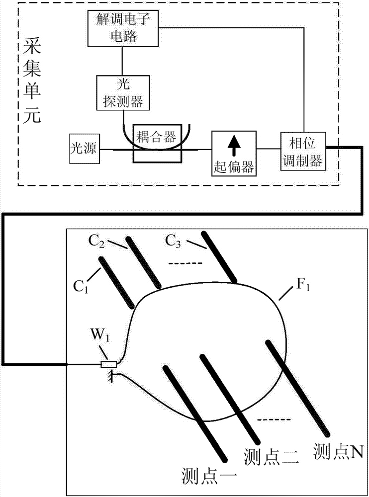
[0048] like Image 6 As shown, it is a set of multi-ring optical CT for measuring neutral point zero-sequence current. 1 、C 2 、C 3 Above, the three sensing rings are connected by polarization maintaining optical fiber 1 . The A-phase fiber optic sensing ring of the all-fiber optic current transformer consists of a λ / 4 wave plate W 1-1 , Sensing fiber F 1 and λ / 4 waveplate W 1-2 Composition; Phase B optical fiber sensing ring consists of λ / 4 wave plate W 2-1 , Sensing fiber F 2 and λ / 4 waveplate W 2-2 Composed; C-phase fiber sensing ring is composed of λ / 4 wave plate W 3 , Sensing fiber F 3 and reflector 2. The sensing fibers of the three sensing fiber rings are wound in the same direction, so they exhibit the same polarity. Let the primary current value in the A-phase optical fiber ring be I A , this current produces a phase shift of φ A ; I in phase B fiber optic ring B Current influence produces a phase shift φ B ; I in phase C fiber ...


PUM


Abstract

The invention discloses a multi-ring all-fiber current transformer comprising an acquisition unit and a plurality of sensing fiber rings. All sensing fiber rings are connected in series and the adjacent sensing fiber rings are connected by polarization-maintaining fibers; and the sensing fiber ring at the front end is connected with the acquisition unit by a polarization-maintaining fiber. The acquisition unit provides an optical signal meeting the need of the sensing fiber ring, receives an optical signal returned by each sensing fiber ring, and calculates a primary current. On the basis of the structure of the transformer, a measurement need of differential currents or combined currents of a plurality of differential-current and zero-sequence-current measurement points can be met with low costs; and the system reliability is improved.

Description

technical field [0001] The invention relates to a structure of an all-fiber current transformer configured with multiple sensing fiber rings. Background technique [0002] In the power system, the calculation of differential current is generally realized by performing differential calculation on the secondary current of two or more current transformers. For primary equipment with different voltage levels and rated currents on each side, such as the main transformer, the selected current transformers are generally of different types and have different transformation ratios, and their dynamic range and transient characteristics may be quite different. On the one hand This leads to a large differential unbalanced current. On the other hand, when an external fault occurs, it is easy to cause differential protection to malfunction. For protected primary equipment such as generators and busbars, current transformers of the same type are generally used, but due to manufacturing er...

Claims


Application Information

Patent Timeline
IPC IPC(8): G01R15/24G01R19/10
CPCG01R15/24G01R19/10
Inventor 王耀阎嫦玲罗苏南须雷赵俊丁晔李权伟王凯王光
Owner NR ELECTRIC CO LTD
Why Eureka
Try Eureka