
Optical modulator module

A light modulator and light modulation technology, applied in the direction of instruments, optics, nonlinear optics, etc., to achieve the effect of good modulation characteristics, suppression of degradation, and less degradation of modulation characteristics

Active Publication Date: 2018-04-06
SUMITOMO OSAKA CEMENT CO LTD
View PDF8 Cites 0 Cited by
  • Summary
  • Abstract
  • Description
  • Claims
  • Application Information

AI Technical Summary

Problems solved by technology

In addition, broadband (higher performance) and higher integration of 400G / 1T optical modulators will be required in the future, so the problem of degradation of modulation characteristics will become a more important issue

Method used


Image

  • Optical modulator module
  • Optical modulator module
  • Optical modulator module

Examples


Embodiment Construction

[0048] Hereinafter, the optical modulator module of the present invention will be described in detail.

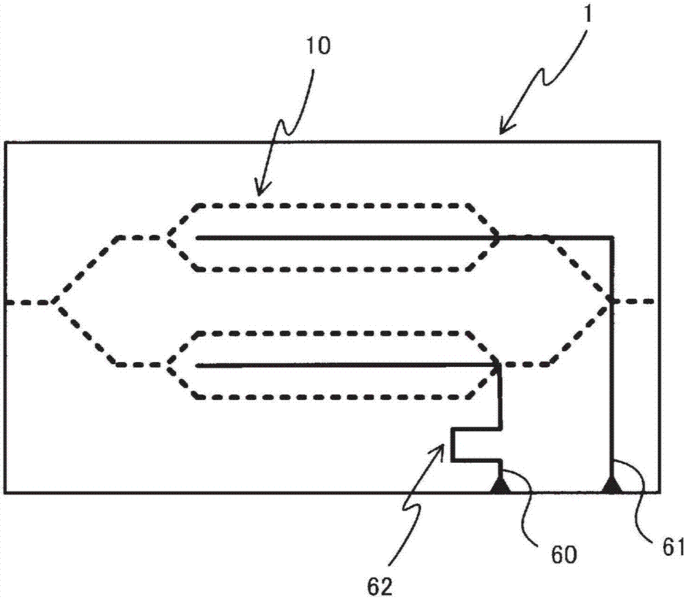
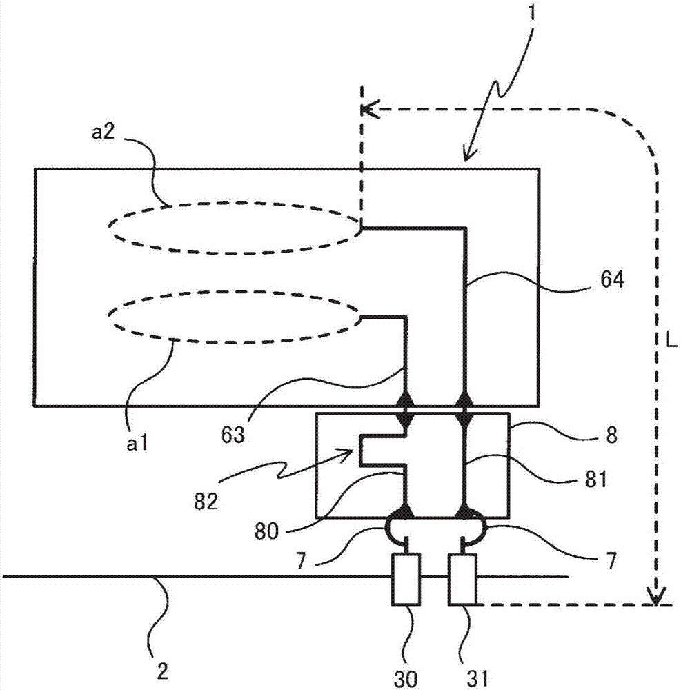
[0049] like Figure 5-7 As shown, the optical modulator module to which the present invention is applied accommodates the modulation substrate (1, 10, 11) having a plurality of optical modulation parts (a1-a4) in the housing, and has a The plurality of signal supply lines for supplying modulation signals to the optical modulation unit by the connector terminal is characterized in that the electrical lengths of at least two or more signal supply lines of the plurality of signal supply lines are set to be different from each other. , in a specific part of the signal supply line, use at least one of the following structures (a) and (b):

[0050] (a) The longer the overall electrical length of the signal supply line is, the wider the cross-sectional area of ​​the surface perpendicular to the propagation direction of the modulated signal is set;

[0051] (b) The cross-sectiona...


PUM


Abstract

The present invention provides an optical modulator module with little deterioration in modulation characteristics. The optical modulator module accommodates a modulation substrate having a pluralityof optical modulation sections in a housing, and includes a plurality of signal supply lines for supplying a modulation signal to the optical modulation section from a connector terminal introduced into the housing. It is characterized in that the electrical lengths of the entire signal supply lines of at least two or more of the plurality of signal supply lines are set to be different from each other; in the specific portion of the signal supply line, at least one of the configurations of the following (a) and (a) are used: a, the longer the electrical length of the entire signal supply line,the wider the cross-sectional area of the plane perpendicular to the direction in which the modulation signal propagates; b, the cross-sectional area of the specific portion is wider than the cross-sectional area of the portion other than the specific portion, and the longer the electrical length of the entire signal supply line is, the longer the length of the specific portion is set.

Description

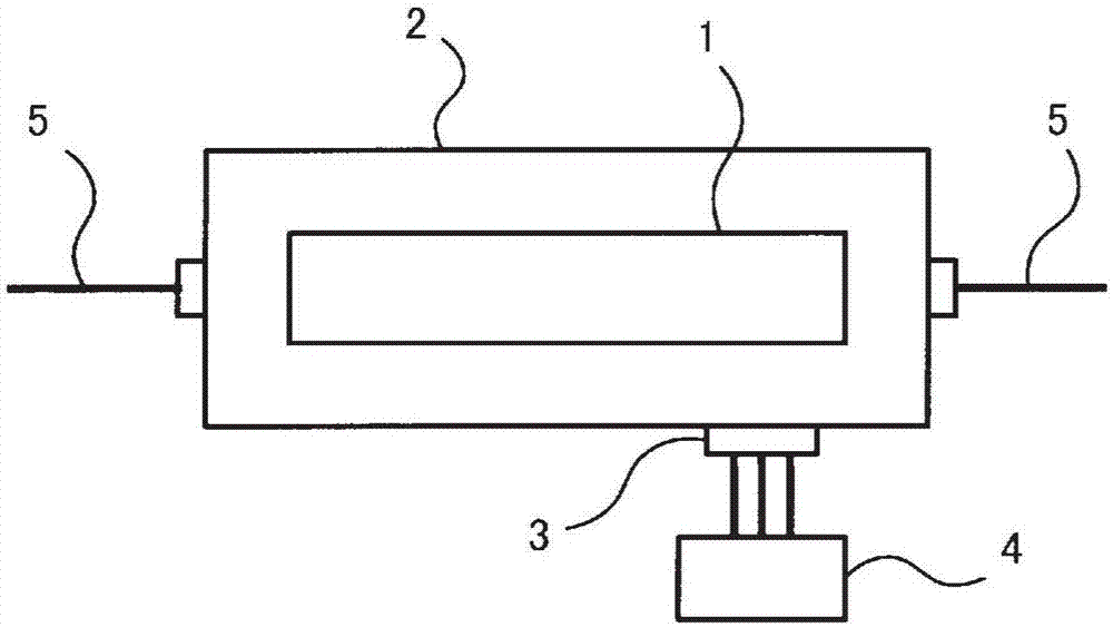
technical field [0001] The present invention relates to an optical modulator module, and more particularly, to an optical modulator module including a plurality of optical modulators and a plurality of signal supply lines for supplying modulation signals to the respective optical modulators. Background technique [0002] Many optical modulators are used in the field of optical communication or the field of optical measurement. In order to transmit high-speed and large-capacity information, whether it is the modulation method of the optical modulator or the QPSK (Quadrature Phase Shift Keying: Positive Multi-value modulation such as DP-QPSK (Dual Polarization-Quadrature Phase Shift Keying) or DP-QPSK (Dual Polarization-Quadrature Phase Shift Keying) or transmission formats that introduce polarization multiplexing to multi-value modulation are also diversified . [0003] like figure 1 As shown, the light modulator module has a structure in which a chip (substrate for modula...

Claims


Application Information

Patent Timeline
Patent Type & Authority Applications(China)
IPC IPC(8): G02F1/03G02F1/035
CPCG02F1/0305G02F1/035G02F1/0102G02F1/011G02F2201/12
Inventor 加藤圭宫崎德一清水亮
Owner SUMITOMO OSAKA CEMENT CO LTD
Learn More