Household rotary electric appliance switch

A technology of electrical switch and rotary type, which is applied in the direction of electrical switches, circuits, electrical components, etc., which can solve the problem of the rotation control block sliding away from the electrical switch, and achieve the effect of preventing the force from detaching from the connecting shaft of the switch

Inactive Publication Date: 2018-04-06
ANHUI KAICHENG ELECTRIC APPLIANCE CO LTD
View PDF4 Cites 2 Cited by
  • Summary
  • Abstract
  • Description
  • Claims
  • Application Information

AI Technical Summary

Problems solved by technology

[0003] In the existing household rotary electrical switch technology, when most of the household rotary electrical switches rotate the rotary control block, the rotary blocks on both sides of the rotary control block are often broken by force, and during long-term use Among them, since most of the control rotating blocks are directly pressed and connected to the electrical switch, the rotating control block is prone to slipping away from the electrical switch. Therefore, we have designed a household rotary electrical switch to solve the problem. above questions

Method used


Image

  • Household rotary electric appliance switch
  • Household rotary electric appliance switch

Examples


Embodiment Construction

[0019] The following will clearly and completely describe the technical solutions in the embodiments of the present invention with reference to the accompanying drawings in the embodiments of the present invention. Obviously, the described embodiments are only some, not all, embodiments of the present invention.

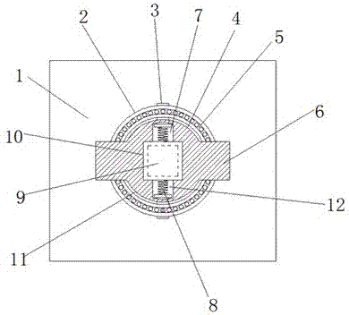
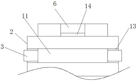
[0020] refer to Figure 1-2 , a household rotary electrical switch, comprising a switch mounting plate 1, a circular mounting groove 4 is arranged on the switch mounting plate 1, an annular fixing plate 2 is arranged on the outer side of the mounting groove 4, and a switch is arranged in the middle of the mounting groove 4 The connecting shaft 9 and the mounting groove 4 are connected with the rotation control block 11 through the switch connection shaft 9, the rotation block 6 is arranged on both sides of the rotation control block 11, and the rotation control block 11 on one side of the two rotation blocks 6 is internally arranged There is a first accommodating cav...


PUM


Abstract

The invention discloses a household rotary electric appliance switch moulding apparatus. The apparatus herein includes a moulding bench. The two sides of the top part of the moulding bench are fixedlyprovided with a support plate. The opposite side surfaces of the two support plates are both fixedly provided with a slide rail. The top parts of the two support plates are fixedly provided with a top plate. The two sides of the top part of each top plate are fixedly provided with a first push rod motor. The middle part of an installation plate is provided with a second push rod motor. A lower end of the second push rod motor is fixedly provided with a pull bar. A lower end of the pull bar is fixedly provided with a slide plate. The two sides of the slide plate are provided with a slide block, and each slide block is slidingly connected to the slide rail. The slide plate slides up and down over the slide rail. The bottom part of the slide plate is fixedly provided with an upper plate through a bolt. The top part of the moulding bench is provided with an installation groove. The two sides of the bottom part of the installation groove are provided with a receiving groove. Each receivinggroove is provided with a third push bar motor therein. The bottom part of the installation groove is provided with a lower plate. According to the invention, the household rotary electric applianceswitch herein has the characteristics of reasonable structure, unique design, novel structure and promotion suitability.

Description

technical field [0001] The invention relates to the field of electrical switches, in particular to a household rotary electrical switch. Background technique [0002] Electrical switch refers to the switch used in low-voltage electrical appliances for infrequently manually switching on and off the circuit, or as the introduction switch of the power supply in the machine tool circuit, which is divided into knife switch, combination switch, etc. [0003] In the existing household rotary electrical switch technology, when most of the household rotary electrical switches rotate the rotary control block, the rotary blocks on both sides of the rotary control block are often broken by force, and during long-term use Among them, since most of the control rotating blocks are directly pressed and connected to the electrical switch, the rotating control block is prone to slipping away from the electrical switch. Therefore, we have designed a household rotary electrical switch to solve ...

Claims


Application Information

Patent Timeline
Patent Type & Authority Applications(China)
IPC IPC(8): H01H19/04H01H19/14
CPCH01H19/04H01H19/14
Inventor 刘开成
Owner ANHUI KAICHENG ELECTRIC APPLIANCE CO LTD
Why Eureka
Try Eureka