Battery system monitoring apparatus

A battery system and monitoring device technology, applied in battery circuit devices, circuit devices, secondary batteries, etc.

Active Publication Date: 2018-04-06
HITACHI ASTEMO LTD
View PDF9 Cites 3 Cited by
  • Summary
  • Abstract
  • Description
  • Claims
  • Application Information

AI Technical Summary

Problems solved by technology

Therefore, in the measurement of the cell voltage during the balancing process, the influence of the voltage drop on the voltage detection line as described above cannot be ignored.

Method used


Image

  • Battery system monitoring apparatus
  • Battery system monitoring apparatus
  • Battery system monitoring apparatus

Examples


no. 1 approach -

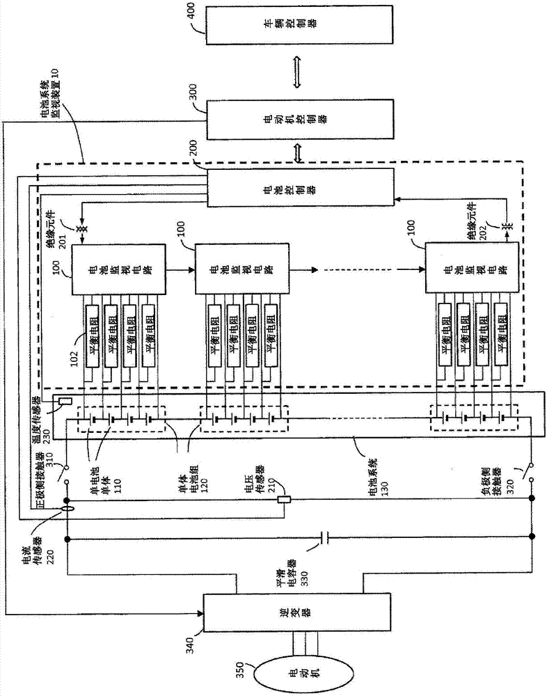
[0024] figure 1 It is a figure which shows the structure of the battery system monitoring apparatus 10 which concerns on one Embodiment of this invention. The battery system monitoring device 10 includes a battery controller 200 and a plurality of battery monitoring circuits 100 connected to each other in a predetermined communication order. The battery system monitoring device 10 is mounted on an electric vehicle such as an electric vehicle or a hybrid vehicle together with the vehicle controller 400 , the motor controller 300 , the battery system 130 , the inverter 340 , and the motor 350 .

[0025] The battery system 130 is a battery system in which a plurality of battery cells 120 are connected in series. Each battery cell group 120 is configured by connecting a plurality of battery cells 110 (hereinafter, sometimes simply referred to as cells) in series. For each cell 110 , for example, a secondary battery such as a lithium ion battery is used.

[0026] In the battery ...

no. 1 approach

[0061] According to the first embodiment of the present invention described above, the following effects can be obtained.

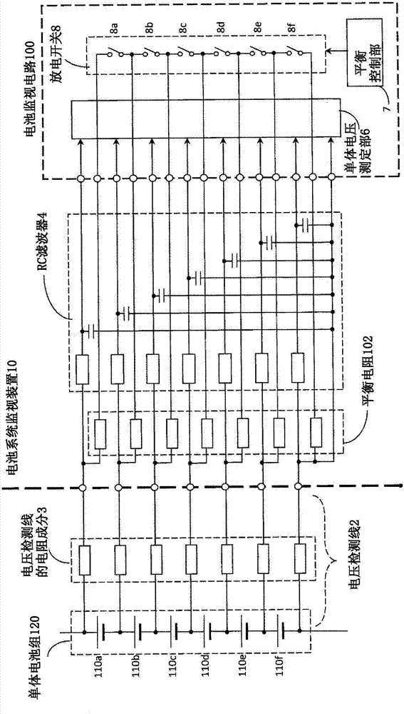
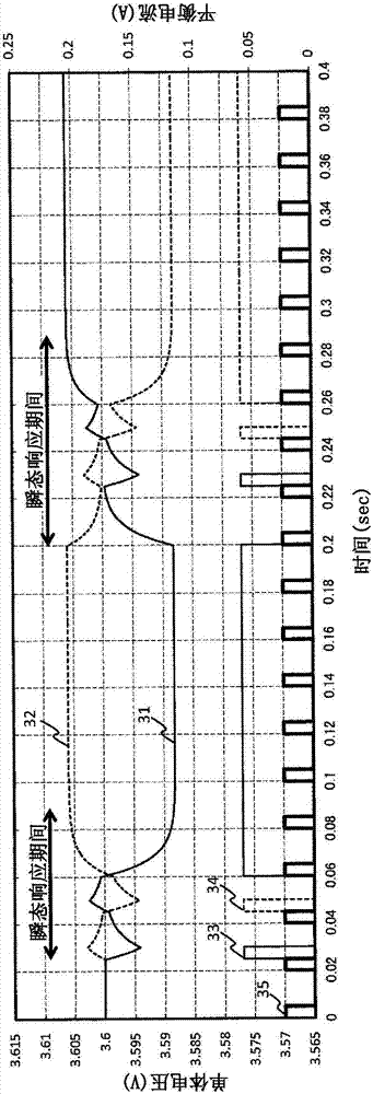
[0062] (1) The battery system 130 includes a plurality of battery packs 120 formed by connecting a plurality of battery cells 110 in series, and the battery system monitoring device 10 for monitoring and controlling the battery system 130 includes Set up the battery monitoring circuit 100. Each battery monitoring circuit 100 has a cell voltage that is connected to both poles of each battery cell 110 of the corresponding battery cell group 120 via a voltage detection line 2, and measures the cell voltage of each battery cell 110 at a predetermined time. Measuring section6. An RC filter 4 including a resistor and a capacitor is connected to the voltage detection line 2 . The cell voltage measurement unit 6 increases the cell voltage measurement interval when the stored charge amount of the capacitor of the RC filter 4 changes. In this manner, management ...

no. 2 approach -

[0067] Next, a second embodiment of the present invention will be described. In the above-mentioned first embodiment, the example in which the measurement timing of the cell voltage is changed when the balancing current is switched has been described. On the other hand, in the second embodiment, an example will be described in which the measurement timing of the cell voltage is changed when the connection state between the voltage detection lines is changed during the diagnosis of the cell voltage measuring unit.

[0068] Figure 7 It is a diagram showing the details of the connection circuit between the unit battery pack 120 and the battery monitoring circuit 100a according to the second embodiment of the present invention. In the battery system monitoring device 10 a of the present embodiment, instead of the battery monitoring circuit 100 described in the first embodiment, a battery monitoring circuit 100 a is provided corresponding to each unit battery pack 120 . Such as ...


PUM


Abstract

The present invention realizes management control of a battery pack using an accurate cell voltage measurement value. A battery system monitoring apparatus 10 that monitors and controls a battery system is provided with a battery monitoring circuit 100 provided for each cell group 120. Each of the battery monitoring circuits 100 is connected to both poles of each unit battery cell 110 of the corresponding cell group 120 via voltage detection lines 2 and has a cell voltage measurement unit 6 that measures the cell voltage of each unit battery cell 110 at prescribed time intervals. An RC filter4 having a resistor and a capacitor is connected to the voltage detection lines 2. When the accumulated electric charge in the capacitor of the RC filter 4 changes, the cell voltage measurement unit 6extends the cell voltage measurement intervals.

Description

technical field [0001] The invention relates to a device for monitoring a battery system. Background technique [0002] In hybrid electric vehicles (HEV) and electric vehicles (EV), in order to secure a desired high voltage, a battery pack (battery system) composed of a large number of battery cells of secondary batteries connected in series is generally used. Conventionally, in such a battery pack, a battery monitoring circuit using an integrated circuit or the like is connected to every predetermined number of battery cells. By using this battery monitoring circuit to measure the voltage between the terminals of each battery cell (cell voltage) and balance (equalize) discharge to equalize the remaining capacity of each battery cell, etc., each battery cell Monitoring and management of the state of the monomer. During the balancing process, each battery cell is discharged according to the remaining capacity, and the discharge current flows to the balance resistor through ...

Claims


Application Information

Patent Timeline
Patent Type & Authority Applications(China)
IPC IPC(8): G01R31/36G01R19/00H01M10/48H02J7/02
CPCH01M10/48H02J7/02G01R31/396Y02E60/10G01R19/00G01R31/36
Inventor 工藤彰彦金井友范有马智行塚本明子
Owner HITACHI ASTEMO LTD
Why Eureka
Try Eureka