Cutting equipment for machining and forming plastic product

A technology for plastic products and molding processing, applied in metal processing and other directions, can solve the problems of low strength, loss and rupture, deformation, etc., and achieve the effect of easy clamping, simple structure, and damage prevention.

Pending Publication Date: 2018-04-10
湖州硕能纺织科技有限公司
View PDF6 Cites 7 Cited by
  • Summary
  • Abstract
  • Description
  • Claims
  • Application Information

AI Technical Summary

Problems solved by technology

[0002] During the processing and molding of plastic products, the continuous plastic products output by the extruder often need to be cut into standard specifications by a cutting device. Among them, tubular plastic products are widely used in people's daily life, because tubular plastic products The middle is a hollow structure, so the strength is lower than that of ordinary plastic products, and it is easy to be deformed or even lost and broken when subjected to external force. However, ordinary cutting devices are not convenient for clamping tubular plastic products, and it is not conducive for workers to cut tubular plastic products. , and the strength of the clamping is mostly judged by the workers based on experience. The clamping force is not easy to control. When the clamping force is too large, it is easy to cause damage to the tubular plastic product and affect the quality of the tubular plastic product. Therefore, we propose a method using Cutting equipment for plastic product molding processing is used to solve the above problems

Method used


Image

  • Cutting equipment for machining and forming plastic product
  • Cutting equipment for machining and forming plastic product
  • Cutting equipment for machining and forming plastic product

Examples


Embodiment Construction

[0021] The following will clearly and completely describe the technical solutions in the embodiments of the present invention with reference to the accompanying drawings in the embodiments of the present invention. Obviously, the described embodiments are only some, not all, embodiments of the present invention.

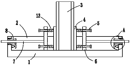
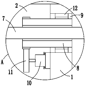
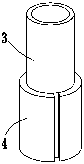
[0022] refer to Figure 1-3 , a kind of cutting equipment used for forming and processing plastic products, comprising a cutting table 1, a clamping groove 2 is opened on the top of the cutting table 1, a tubular plastic product 3 is placed in the clamping groove 2, two pieces of the tubular plastic product 3 Both sides are in contact with arc-shaped plates 4, and the arc-shaped plates 4 are slidably installed in the clamping groove 2. The sides of the two arc-shaped plates 4 that are far away from each other are welded with two buffer rods 5, which are located on the same side of the tubular plastic product 3 The outer sides of the two buffer rods 5 are slidingly in...


PUM


Abstract

The invention discloses cutting equipment for machining and forming a plastic product. The cutting equipment comprises a cutting table, wherein a clamping groove is formed in the top of the cutting table; a tubular plastic product is placed in the clamping groove, arc-shaped plates are in contact with the two sides of the tubular plastic product respectively, and the arc-shaped plates are slidingly arranged in the clamping groove; the sides, far away from each other, of the two arc-shaped plates are each provided with two buffer rods; the outer sides of every two buffer rods located on the same side of the tubular plastic product are slidingly provided with one pushing plate; screw rods are welded to the sides, far away from the tubular plastic product, of the pushing plates, and sleeves are screwed to the outer sides of the screw rods; and rotating holes are formed in the inner walls of the two sides of the clamping groove. According to the cutting equipment, the structure is simple,and the tubular plastic product can be conveniently clamped; and the strength of the clamping force between the arc-shaped plates and the tubular plastic product can be determined by observing the deformation of buffer springs, so that damage to the tubular plastic products is prevented, and the use by people is facilitated.

Description

technical field [0001] The invention relates to the technical field of cutting equipment for plastic products, in particular to a cutting equipment for molding and processing plastic products. Background technique [0002] During the processing and molding of plastic products, the continuous plastic products output by the extruder often need to be cut into standard specifications by a cutting device. Among them, tubular plastic products are widely used in people's daily life. The middle is a hollow structure, so the strength is lower than that of ordinary plastic products, and it is easy to be deformed or even lost and broken when subjected to external force. However, ordinary cutting devices are not convenient for clamping tubular plastic products, and it is not conducive for workers to cut tubular plastic products. , and the strength of the clamping is mostly judged by the workers based on experience. The clamping force is not easy to control. When the clamping force is to...

Claims


Application Information

Patent Timeline
Patent Type & Authority Applications(China)
IPC IPC(8): B26D7/02
CPCB26D7/02B26D2007/013
Inventor 尉本奇
Owner 湖州硕能纺织科技有限公司
Why Eureka
Try Eureka