Continuous IC burning device and burn method thereof

A programming socket and pin technology, applied in transportation and packaging, conveyors, software deployment, etc., can solve the problems of long manual operation time, cumbersome operation, single IC programming, etc., and achieve a high degree of automation.

Active Publication Date: 2018-04-10
HUIZHOU JUNYA DIGITAL TECH CO LTD
View PDF11 Cites 2 Cited by
  • Summary
  • Abstract
  • Description
  • Claims
  • Application Information

AI Technical Summary

Problems solved by technology

[0002] At present, the operation of the existing programming equipment is relatively cumbersome, and only a single IC can be programmed. Since the shapes of the ICs are not the same, the same set of transmission devices cannot be used for transmission, so they can only be loaded into the programming socket one by one for operation. The operation time is long and the cost is high, so there is an urgent need for an IC programming device with low cost and continuous programming

Method used


Image

  • Continuous IC burning device and burn method thereof

Examples


Embodiment 1

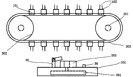
[0023] like figure 1 As shown, this embodiment provides an IC continuous programming device, which is characterized in that it includes: IC: including a chip 101 and a pin 102, the pin 102 is arranged on the surface of the chip 101, and the chip 101 and the pin 102 are connected in communication; Burner: The burner includes a data output unit 201, a base 202 and a burner base 203, the data output unit 201 is set in the base 202, the burner base 203 is set on the surface of the base 202, and the burner base 203 is connected to the boot The shape of the pin 102 is matched; the data output unit 201 is connected with the programming seat 203; the transmission assembly: includes a stepping motor 301, a transmission gear 302 and a transmission belt 303; the output shaft of the stepping motor 301 is connected with the transmission gear 302 axis, step The feeder motor 301 can drive the transmission gear 302 to rotate along the axis of the transmission gear 302; the inside of the trans...

Embodiment 2

[0030] This embodiment provides an IC continuous programming device, including: IC: including a chip 101 and pins 102, the pins 102 are arranged on the surface of the chip 101, and the chip 101 and the pins 102 are connected in communication; burner: burner Including a data output unit 201, a base 202 and a burning base 203, the data output unit 201 is arranged in the base 202, the burning base 203 is arranged on the surface of the base 202, and the burning base 203 matches the shape of the pin 102; the data The output unit 201 is communicatively connected with the programming seat 203; the transmission assembly: includes a stepping motor 301, a transmission gear 302 and a transmission belt 303; the output shaft of the stepping motor 301 is connected to the transmission gear 302 axis, and the stepping motor 301 can drive the transmission gear 302 rotates along the axis of the transmission gear 302; the inside of the transmission is provided with a protrusion that meshes with th...

Embodiment 3

[0032] This embodiment provides an IC continuous programming device, including: IC: including a chip 101 and pins 102, the pins 102 are arranged on the surface of the chip 101, and the chip 101 and the pins 102 are connected in communication; burner: burner Including a data output unit 201, a base 202 and a burning base 203, the data output unit 201 is arranged in the base 202, the burning base 203 is arranged on the surface of the base 202, and the burning base 203 matches the shape of the pin 102; the data The output unit 201 is communicatively connected with the programming seat 203; the transmission assembly: includes a stepping motor 301, a transmission gear 302 and a transmission belt 303; the output shaft of the stepping motor 301 is connected to the transmission gear 302 axis, and the stepping motor 301 can drive the transmission gear 302 rotates along the axis of the transmission gear 302; the inside of the transmission is provided with a protrusion that meshes with th...


PUM


Abstract

The invention provides a continuous IC burning device. The device comprises an IC, a burner and a conveyor assembly, wherein the IC comprises chips and pins, the pins are arranged on the surfaces of the chips, the chips are in communication connection with the pins, the burner comprises a data output unit, a base and a burning base, the data output unit is arranged in the base, the burning base isarranged on the surface of the base, the burning base is matched with each pin in shape, the data output unit and the burning base are in communication connection, the conveyor assembly comprises stepping motors, conveyor gears and a conveyor belt, the output shafts of the stepping motors are in axial connection with the conveyor gears, the stepping motors can drive the conveyor gears to rotate along the axes of the conveyor gears, bulges meshed with the conveyor gears are arranged on the inner side of the conveyor belt, grooves matched with the chips in shape are formed in the outer side ofthe conveyor belt, the chips are embedded into the outer side of the conveyor belt, the pins are exposed on the outer portion of the conveyor belt, and the burning base is located under the conveyor belt. The IC burning device is capable of continuous burning and low in cost.

Description

technical field [0001] The invention relates to a burning device, in particular to an IC continuous burning device and a burning method thereof. Background technique [0002] At present, the operation of the existing programming equipment is relatively cumbersome, and only a single IC can be programmed. Since the shapes of the ICs are not the same, the same set of transmission devices cannot be used for transmission, so they can only be loaded into the programming socket one by one for operation. The operation time is long and the cost is high, so there is an urgent need for an IC programming device with low cost and continuous programming. Contents of the invention [0003] In view of this, the present invention provides a low-cost IC continuous programming device. [0004] The present invention mainly realizes through the following technical solutions: [0005] An IC continuous programming device is characterized in that it includes: IC: including a chip and pins, the ...

Claims


Application Information

Patent Timeline
Patent Type & Authority Applications(China)
IPC IPC(8): G06F8/61B65G15/30
CPCG06F8/61B65G15/30
Inventor 樊领邹乾坤刘继承
Owner HUIZHOU JUNYA DIGITAL TECH CO LTD
Why Eureka
Try Eureka