
Machining method of spiral groove

A processing method and a technology of spiral grooves, which are applied in metal processing equipment, manufacturing tools, turning equipment, etc., can solve the problems of low processing efficiency and error-prone, and achieve convenient operation, high precision, and easy processing of groove width and groove depth. big effect

Inactive Publication Date: 2018-04-13
WUHAN MARINE MACHINERY PLANT
View PDF5 Cites 3 Cited by
  • Summary
  • Abstract
  • Description
  • Claims
  • Application Information

AI Technical Summary

Problems solved by technology

[0006] In order to solve the problems in the prior art that manual modification of instructions is required after each processing, processing efficiency is low, and errors are prone to errors, the embodiment of the present invention provides a processing method for spiral grooves

Method used


Image

  • Machining method of spiral groove
  • Machining method of spiral groove
  • Machining method of spiral groove

Examples


Embodiment Construction

[0044] In order to make the object, technical solution and advantages of the present invention clearer, the implementation manner of the present invention will be further described in detail below in conjunction with the accompanying drawings.

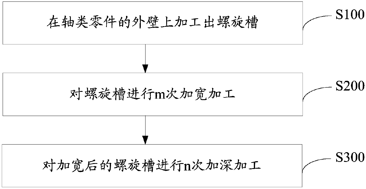
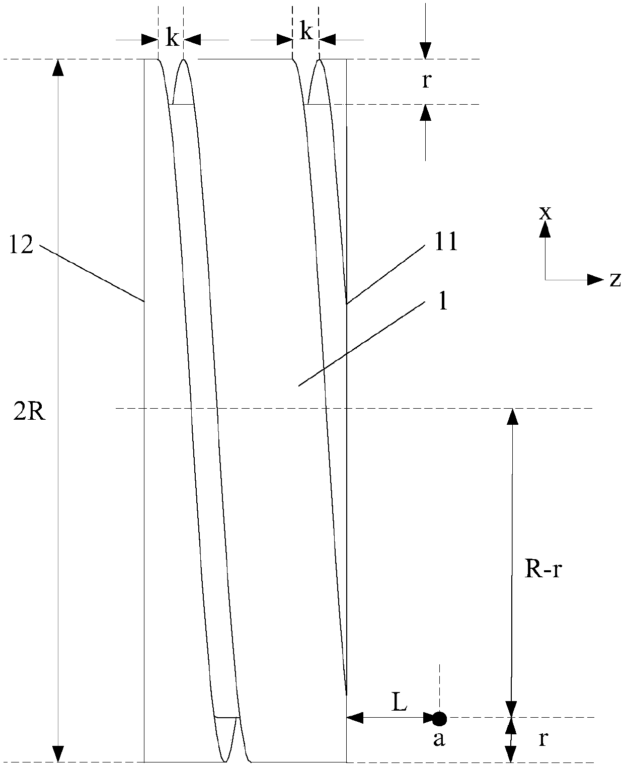
[0045] figure 1 It is a method flow chart of a method for processing a spiral groove provided by an embodiment of the present invention. The method is suitable for processing a spiral groove with a groove width D and a groove depth H on the outer wall of a shaft part. Among them, preferably H≥18mm, preferably D≥15mm, the processing method provided by the embodiment of the present invention is especially suitable for processing spiral grooves with large groove width and groove depth. In this embodiment, the radius R of the shaft part is 156.2mm.

[0046] Such as figure 1 As shown, the processing method includes:

[0047] S100: Machining a spiral groove on the outer wall of the shaft part.

[0048] Among them, the groove width of the...


PUM


Abstract

The invention discloses a machining method of a spiral groove, and belongs to the field of mechanical machining. The machining method comprises the steps that the spiral groove is machined in the outer wall of a shaft part, the groove width of the spiral groove is equal to the edge width k of a cutter, the screw pitch of the spiral groove is P, and the groove depth of the spiral groove is r; widening machining is conducted on the spiral groove by m times, the groove width of the spiral groove is increased by J every widening machining until the groove width of the spiral groove reaches D, andthe groove depth is r; and deepening machining is conducted on the widened spiral groove by n times, the groove depth of the spiral groove is increased by r every deepening machining until the groovedepth of the spiral groove reaches H, and the groove width reaches D. Because machining is conducted by adopting a mode of multi-time repeated turning in the processes of m-time widening machining andn-time deepening machining, the engagement of the cutting edge of every cutting is low, the precision of the machined spiral groove is higher, machining is conducted conveniently through a digital controlled lathe, by changing the frequency numbers of repeating m and n, the groove width and the groove depth of the machined spiral groove can be changed, and operation is convenient.

Description

technical field [0001] The invention relates to the field of mechanical processing, in particular to a method for processing a spiral groove. Background technique [0002] Spiral grooves are usually provided on many bushing parts. [0003] At present, there are mainly two methods for processing spiral grooves. One is to process spiral grooves cyclically through the threading process that comes with the CNC lathe system. Another method is to use the G33 or G32 command in the G code for processing. [0004] In the process of realizing the present invention, the inventor finds that there are at least the following problems in the prior art: [0005] Due to the few adjustable parameters of the system's own process, the adjustment is inconvenient, and the threading process that comes with the CNC lathe system can only process narrower spiral grooves. The processing with G33 or G32 command is only suitable for processing narrower spiral grooves. Both methods are not suitable f...

Claims


Application Information

Patent Timeline
IPC IPC(8): B23B1/00B23B5/48G06F17/50
CPCB23B1/00B23B5/48G06F30/17
Inventor 刘洪波付跃飞王充聪熊永钊蒋耘哲吴红琼
Owner WUHAN MARINE MACHINERY PLANT
Learn More