Chamfering machine

A chamfering machine and bevel technology, applied in the field of chamfering machines, can solve the problems of high cost, inconvenient assembly of parts, poor chamfering effect, etc., and achieve the effect of low cost, simple structure and good chamfering effect

Inactive Publication Date: 2018-04-13
涂壹强
View PDF0 Cites 2 Cited by
  • Summary
  • Abstract
  • Description
  • Claims
  • Application Information

AI Technical Summary

Problems solved by technology

[0002] There are usually burrs on the machined workpiece, which is not convenient for parts assembly. Therefore, chamfering is generally made on the end of the workpiece. An important function of chamfering is to remove burrs and make it easy to install. In addition, chamfering can also play a role It can be seen that the chamfering on the workpiece plays a very important role in reducing the stress concentration and strengthening the strength of the parts. However, the chamfering machines on the market are complex in structure, expensive in cost, and poor in chamfering effect.

Method used


Image

  • Chamfering machine
  • Chamfering machine

Examples


Embodiment Construction

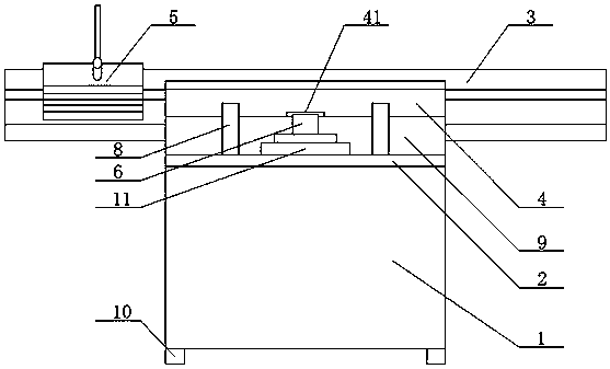
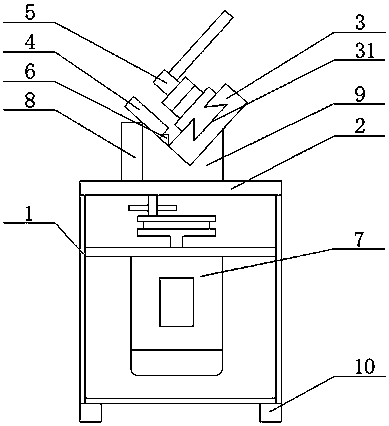
[0016] see Figure 1-Figure 2 As shown, the technical solution adopted in this specific embodiment is: it includes a box body 1, a workbench 2, a guide plate 3, an inclined surface 4, a locking device 5, a milling cutter 6, a motor 7, a fixing part 8, a supporting part 9, Chassis 11, workbench 2 are arranged on the upper surface of box body 1, the inside of box body 1 is provided with motor 7, the upper surface of workbench 2 is provided with support part 9, and the upper surface of support part 9 is V-shaped structure, guide plate 3 It is arranged on one side slope of the V-shaped structure on the surface of the support part 9, the slope 4 is arranged on the other side slope of the V-shaped structure on the surface of the support part 9, the locking device 5 is arranged on the upper surface of the guide plate 3, and on the workbench 2 A chassis 11 is arranged at the center of the surface, a milling cutter 6 is arranged above the chassis, and fixing parts 8 are arranged on bot...


PUM


Abstract

A chamfering machine relates to the field of mechanical technology, in particular to a chamfering machine. It includes a box body, a workbench, a guide plate, an inclined plane, a locking device, a milling cutter, a motor, a fixing part, a support part, and a chassis. The upper surface of the support part is provided with a support part, the upper surface of the support part is a V-shaped structure, the guide plate is set on one side of the V-shaped structure on the support surface, the slope is set on the other side of the V-shaped structure on the support surface, and locked The device is arranged on the upper surface of the guide plate, a chassis is arranged at the center of the upper surface of the workbench, a milling cutter is arranged above the chassis, and fixing parts are arranged on both sides of the chassis. After adopting the above technical solution, the beneficial effects of the present invention are: the structure is simple, the cost is low, and the chamfering effect is good.

Description

technical field [0001] The invention relates to the field of mechanical technology, in particular to a chamfering machine. Background technique [0002] There are usually burrs on the machined workpiece, which is not convenient for parts assembly. Therefore, chamfering is usually made on the end of the workpiece. An important function of chamfering is to remove burrs and make it easy to install. In addition, chamfering can also play a role It can be seen that the chamfering on the workpiece plays a very important role in reducing the stress concentration and strengthening the strength of the parts. However, the chamfering machines on the market are complex in structure, expensive in cost, and poor in chamfering effect. Contents of the invention [0003] The object of the present invention is to provide a chamfering machine aiming at the defects and deficiencies of the prior art, which has simple structure, low cost and good chamfering effect. [0004] In order to achieve ...

Claims


Application Information

Patent Timeline
Patent Type & Authority Applications(China)
IPC IPC(8): B23C3/12B23Q3/06B23Q5/38
CPCB23C3/126B23Q3/06B23Q5/385
Inventor 涂壹强
Owner 涂壹强
Why Eureka
Try Eureka