Shaft part center aligning mechanism

A technology of parts and shafts, applied in the field of center alignment mechanism, can solve problems such as not being able to meet the alignment requirements of different parts

Pending Publication Date: 2018-04-13
重庆朗奥机械有限公司
View PDF11 Cites 0 Cited by
  • Summary
  • Abstract
  • Description
  • Claims
  • Application Information

AI Technical Summary

Problems solved by technology

[0003] Aiming at the deficiencies in the prior art, the purpose of the present invention is to provide a center alignment mechanism for shaft par...

Method used


Image

  • Shaft part center aligning mechanism
  • Shaft part center aligning mechanism
  • Shaft part center aligning mechanism

Examples


Embodiment

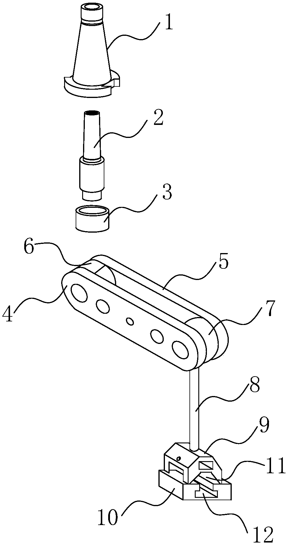
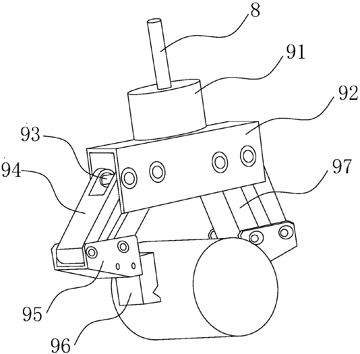
[0026] refer to Figure 1 ~ Figure 4 Shown: a center alignment mechanism for shaft parts, including a taper shank 1 used to connect with the machine tool, a shank 2 sleeved in the taper shank 1, a sliding sleeve 3 connected with the shank 2, Also includes a connecting frame 4, said connecting frame 4 includes two shaped fixed plates 5 arranged symmetrically to each other, the two shaped fixed plates 5 are connected by two limiting rotating parts, and one of the limiting rotating parts 7 is rotationally connected with it There is a rotating rod 8, the lower end of the rotating rod 8 is connected with a workpiece clamping structure 9 with a V-shaped clamping mouth, and a base 10 is provided at a corresponding position below the workpiece clamping structure 9, and the base 10 is connected with the V-shaped A T-shaped slot 12 is formed at a position corresponding to the opening 11; another limiting rotating member 6 is rotationally connected with the handle 2; After the taper han...


PUM


Abstract

The invention discloses a shaft part center aligning mechanism. The shaft part center aligning mechanism comprises a taper handle for connecting with a machine tool, a handle rod sleeved in the taperhandle, and a slide sleeve connected with the handle rod. The shaft part center aligning mechanism further comprises a connecting frame; the connecting frame comprises two strip fixed plates symmetrically arranged; the two strip fixed plates are connected through two limiting rotation pieces; one limiting rotation piece is rotationally connected with a rotating rod; the lower end of the rotating rod is connected with a workpiece clamping structure with a V-shaped clamping port; a base is arranged in a corresponding position below the workpiece clamping structure; the base is provided with a T-shaped groove in a position corresponding to the V-shaped opening; the other rotation piece is rotationally connected with the handle rod; and the handle rod and the rotating rod are opposite in arrangement direction, and are staggered from each other.

Description

technical field [0001] The invention relates to a center alignment mechanism, in particular to a center alignment mechanism for shaft parts. Background technique [0002] In the field of mechanical processing, when using CNC milling machines to process parts, it is necessary to use auxiliary tools such as edge patrols and lever gauges to find out the processing datum of parts. When machining rotary parts on vertical milling machines, it is necessary to clamp the lever gauge on the drill bit The center of the circle of the rotary part is used as the datum of part processing. During the alignment process, it is necessary to adjust the head of the lever gauge to meet the needs of aligning parts with different diameters. However, because the adjustment range of the lever gauge head is very limited, only the inner hole with a smaller diameter can be aligned, and the diameter cannot be aligned. The inner hole exceeds the adjustment range of the meter head. At the same time, the l...

Claims


Application Information

Patent Timeline
IPC IPC(8): B23Q17/22
CPCB23Q17/2233
Inventor 陈东陈庆陈荣
Owner 重庆朗奥机械有限公司
Why Eureka
Try Eureka