Pipe end face polishing device

A technology for end faces and pipes, which is applied in the field of pipe end face grinding devices. It can solve the problems of waste dust and dust environment, human hazards, grinding stability and poor processability, and achieve the effects of stable transportation, improved processing cleanliness, and improved processing accuracy.

Inactive Publication Date: 2018-04-13
季元吉
View PDF5 Cites 8 Cited by
  • Summary
  • Abstract
  • Description
  • Claims
  • Application Information

AI Technical Summary

Problems solved by technology

[0003] After the pipe is cut and welded, the pipe port generally needs to be polished. The existing manual grinding has relatively poor stability and processability, and the waste and dust generated during processing will cause harm to the environment and human body.

Method used


Image

  • Pipe end face polishing device
  • Pipe end face polishing device
  • Pipe end face polishing device

Examples


Embodiment Construction

[0020] The following will clearly and completely describe the technical solutions in the embodiments of the present invention with reference to the accompanying drawings in the embodiments of the present invention. Obviously, the described embodiments are only some, not all, embodiments of the present invention. Based on the embodiments of the present invention, all other embodiments obtained by persons of ordinary skill in the art without making creative efforts belong to the protection scope of the present invention.

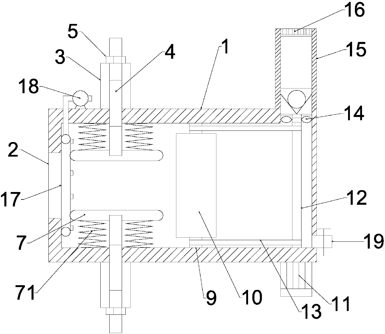
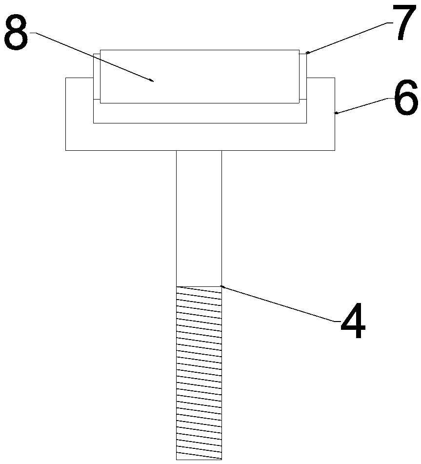
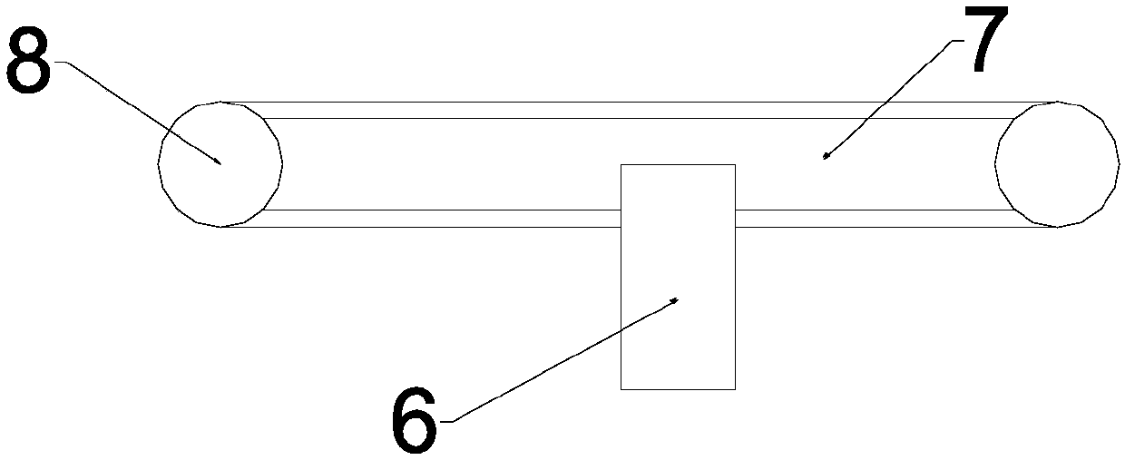
[0021] see Figure 1~3 , in an embodiment of the present invention, a pipe end surface grinding device includes a housing 1, the middle part of the left end of the housing 1 is provided with a pipe inlet 2, and the left part of the upper and lower ends of the housing 1 is vertically welded and provided with a sleeve 3. A threaded rod 4 is provided for sliding fit in the sleeve 3, the upper periphery of the threaded rod 4 is located above the sleeve 3 and conne...


PUM


Abstract

The invention discloses a pipe end face polishing device which comprises a shell. A pipe feeding opening is formed in the left end of the shell. The left portion of the upper end and the left portionof the lower end of the shell are provided with pipe sleeves, thread rods, control nuts, U-shaped supporting plates, horizontal supporting plates, supporting springs and wheel axles. A rotating shaftand a polishing wheel axle are arranged on the middle portion of the inner wall of the shell. The right portion of the lower side of the shell is provided with a motor. A transmission shaft is arranged at the output end of the motor. A transmission belt is arranged between the periphery of the transmission shaft and the rotating shaft. The upper wall of the shell is provided with a dust collectingcylinder. Ventilating fan vanes are arranged at the upper end of the periphery of the transmission shaft. The dust collecting cylinder is provided with an air output cover. The left wall of the shellis provided with an air injecting pipe. An air pump is arranged on the left side of the upper end of the shell. The pipe end face polishing device can be pushed into a pipeline stably and machine theend face flexibly, and meanwhile impurities and tail gas can be cleaned fast and synchronously.

Description

technical field [0001] The invention relates to a pipe processing device, in particular to a pipe end surface grinding device. Background technique [0002] Pipe is the material used to make pipe fittings. Different pipe fittings use different pipe materials, and the quality of the pipe directly determines the quality of the pipe fittings. Such pipes are often used in construction projects, power plants, chemical plants, etc. There is an implementation standard GB / T5310, for high-pressure boilers: there is an implementation standard GB / T8163, seamless steel pipes for conveying fluids: there is an implementation standard GB3087, seamless steel pipes for low-pressure boilers : There is the implementation standard GB / T9948, seamless steel pipe for petroleum cracking: there is the implementation standard GB / T14976, stainless steel seamless steel pipe for fluid transportation, common materials are alloy (15CrMo, 12Cr1MoV) carbon steel (10#, 20#, 45# ) stainless steel (304, 316)...

Claims


Application Information

Patent Timeline
Patent Type & Authority Applications(China)
IPC IPC(8): B24B7/16B24B55/06B24B55/12
CPCB24B7/16B24B55/06B24B55/12
Inventor 季元吉
Owner 季元吉
Why Eureka
Try Eureka