
Chemical industry waste incinerator

A technology for incinerators and waste products, applied in the direction of incinerators, combustion methods, combustion types, etc., can solve problems such as air pollution, energy waste, a large amount of black smoke and dust, and achieve the effects of preventing air pollution, sufficient incineration, and reducing waste

Inactive Publication Date: 2018-04-13
王洁琳
View PDF9 Cites 5 Cited by
  • Summary
  • Abstract
  • Description
  • Claims
  • Application Information

AI Technical Summary

Problems solved by technology

However, most of the existing incinerators do not take into account the use of the heat generated by the incineration of chemical waste, resulting in a waste of energy, and most of the incinerators do not properly collect and treat the gas generated by the combustion of waste products, which will cause air pollution, and the existing After the incinerator burns waste for a long time, there will be waste accumulation and insufficient incineration. There will be moisture problems in the added waste, and a large amount of black smoke and dust will appear during incineration. Therefore, a chemical waste incinerator is now needed , the heat generated by the incinerator can be absorbed by the cooling water installed in the cavity to reduce energy waste, and the gas generated in the incinerator can be treated by the smoke and dust waste gas treatment device to prevent air pollution from being discharged. The heater passes the processed gas into the feed pipe, which can dry the incoming waste, and the auxiliary incineration device can incinerate more fully

Method used


Image

  • Chemical industry waste incinerator
  • Chemical industry waste incinerator
  • Chemical industry waste incinerator

Examples


Embodiment Construction

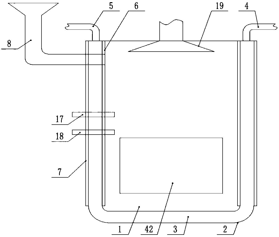
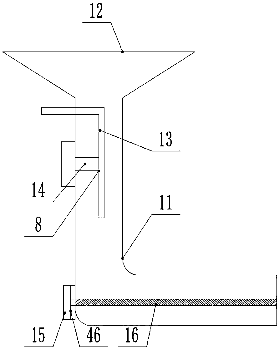
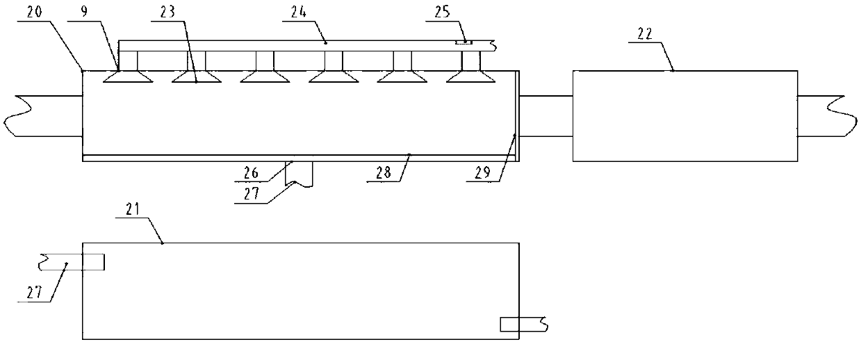
[0021] The present invention is specifically described below in conjunction with accompanying drawing, as Figure 1-5As shown, a chemical waste incinerator includes an incinerator body 1 and a U-shaped shell 2 arranged at the outer ends of both sides of the incinerator body 1, and a cavity 3 is formed between the incinerator body 1 and the U-shaped shell 2 One port of the cavity 3 is connected to the external water supply device through the water injection pipe 4, the other port of the cavity 3 is connected to the water vapor collection device through the exhaust pipe 5, and the inner wall of the incinerator body 1 is provided with a high-temperature refractory layer 6, The outer wall of the U-shaped shell 2 is provided with an anti-scalding protective layer 7, and the outer walls of both sides of the incinerator body 1 are respectively provided with a feeding device 8 and a smoke and dust waste gas treatment device 9, and an auxiliary incineration device 10 is provided at the ...


PUM


Abstract

The invention discloses a chemical industry waste incinerator including an incinerator body and an outer shell. Outer side of two sides of the incinerator body is provided with a feeding device and asmoke and waste gas treating device, the lower end of the incinerator body is provided with an auxiliary incinerator, and the feeding device is composed of an L-shaped feeding pipe, a feeding funnel,an inverted L-shaped material-controlling panel, an electronic pushing rod and an auxiliary feeding device; an inner cavity of the incinerator body is provided with an igniter and an auxiliary ignition device, the smoke and waste gas treating device is composed of an air-inducing cover, a smoke treating tank, a water storage tank and a waste gas treating device, and the lower end of the inner cavity of the incinerator body is provided with an auxiliary incinerator which is composed of a lifting air cylinder, a supporting plate, a incineration baseplate, a reset spring and a spiral stirring device; and the rear end surface of the incinerator body is provided with a pressure fan, and the front end surface of the incinerator body is provided with a load and unload door. The chemical industrywaste incinerator has the beneficial effects of simple structure and strong practicability.

Description

technical field [0001] The invention relates to the field of chemical equipment, in particular to a chemical waste incinerator. Background technique [0002] The incinerator is a kind of chemical equipment used to incinerate combustible chemical waste. After the incinerated chemical waste is discharged, it will effectively reduce the pollution to the environment. However, most of the existing incinerators do not take into account the use of the heat generated by the incineration of chemical waste, resulting in a waste of energy, and most of the incinerators do not properly collect and treat the gas generated by the combustion of waste products, which will cause air pollution, and the existing After the incinerator burns waste for a long time, there will be waste accumulation and insufficient incineration. There will be moisture problems in the added waste, and a large amount of black smoke and dust will appear during incineration. Therefore, a chemical waste incinerator is n...

Claims


Application Information

Patent Timeline
Patent Type & Authority Applications(China)
IPC IPC(8): F23G5/00F23G5/44F23G5/46F23J15/02F23J15/04
CPCF23G5/006F23G5/44F23G5/46F23J15/025F23J15/04
Inventor 王洁琳
Owner 王洁琳
Learn More