
In-situ thrust calibrating device for axial thrust of inclined nozzle

An oblique nozzle and in-situ calibration technology, which is applied in the calibration/testing of force/torque/power measuring instruments, measuring devices, jet engine testing, etc., can solve problems such as errors and inability to calibrate the system, and achieve the method of adding force Reliable, improved calibration accuracy, the effect of high thrust calibration accuracy

Active Publication Date: 2018-04-13
XIAN AEROSPACE PROPULSION TESTING TECH RES INST
View PDF5 Cites 5 Cited by
  • Summary
  • Abstract
  • Description
  • Claims
  • Application Information

AI Technical Summary

Problems solved by technology

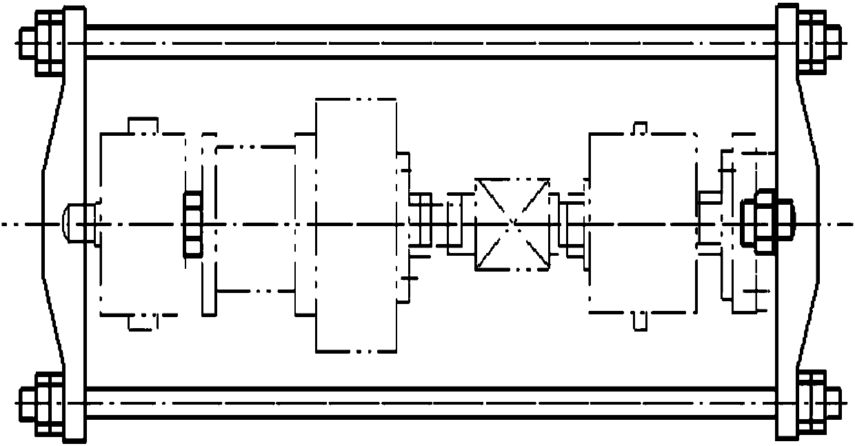
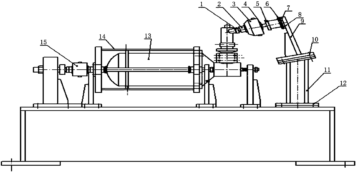
[0005] In order to solve the problem that the system error caused by the frictional resistance generated by the component force of the engine thrust in the vertical direction cannot be calibrated when the existing in-situ calibration method is used to calibrate the engine thrust of the inclined swing nozzle, the present invention proposes an oblique The thrust in-situ calibration device with the axial force of the nozzle is installed. By comparing with the method of axial force of the combustion chamber, the influence of the test stand on the measurement of the engine thrust is determined, and the thrust calibration problem of the inclined swinging nozzle engine is solved, and the thrust is improved. The calibration accuracy meets the thrust in-situ calibration requirements of a rolling control engine ground ignition test

Method used


Image

  • In-situ thrust calibrating device for axial thrust of inclined nozzle
  • In-situ thrust calibrating device for axial thrust of inclined nozzle
  • In-situ thrust calibrating device for axial thrust of inclined nozzle

Examples


Embodiment Construction

[0025] Embodiments of the present invention are described in detail below, examples of which are shown in the drawings, wherein the same or similar reference numerals designate the same or similar elements or elements having the same or similar functions throughout. The embodiments described below by referring to the figures are exemplary and are intended to explain the present invention and should not be construed as limiting the present invention.

[0026] In describing the present invention, it should be understood that the terms "center", "longitudinal", "transverse", "length", "width", "thickness", "upper", "lower", "front", " Orientation indicated by rear, left, right, vertical, horizontal, top, bottom, inside, outside, clockwise, counterclockwise, etc. The positional relationship is based on the orientation or positional relationship shown in the drawings, which is only for the convenience of describing the present invention and simplifying the description, rather than ...


PUM


Abstract

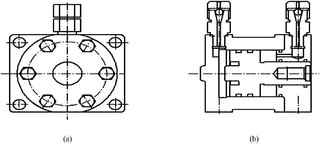
The invention provides an in-situ thrust calibrating device for the axial thrust of an inclined nozzle. The in-situ thrust calibrating device comprises a nozzle positioning plate, a standard sensor, athrust-applying oil cylinder, an oil cylinder positioning and adjusting mechanism, an oil cylinder bracket and an oblique support. The oblique support is mounted on a fixed frame. An intersection angle between the upper connecting flange plane of the oblique support and the axis of the combustion chamber of an engine is equal to an inclination angle between the axis of the inclined nozzle and theaxis of the combustion chamber of the engine. The oil cylinder bracket is fixedly installed on the oblique support. The oil cylinder positioning and adjusting mechanism is fixedly installed on the oil cylinder bracket. The thrust-applying oil cylinder is fixedly installed on the end face of the oil cylinder positioning and adjusting mechanism. The position of the axis of the thrust-applying oil cylinder can be adjusted by connecting lugs on the four sides of end face of the oil cylinder positioning and adjusting mechanism. The front end of the thrust-applying oil cylinder is coaxially connected to the standard sensor through an oil cylinder joint. The front end of the standard sensor coaxially cooperates with the nozzle positioning plate via a ball joint. The nozzle positioning plate is installed on the outlet end surface of the inclined nozzle, and the axis of the nozzle is the same as the axis of the nozzle positioning plate. The in-situ thrust calibrating device can calibrate a system error caused by the frictional resistance due to the component force of the engine thrust force in the vertical direction.

Description

technical field [0001] The invention relates to the technical field of static test thrust measurement of solid rocket motors, in particular to a thrust in-situ calibration device for axial force application of inclined nozzles. Background technique [0002] As an important parameter to measure the external ballistic performance of solid rocket motor, engine thrust is the most important test parameter for engine ground performance test. The calibration before the test, especially the in-situ calibration can eliminate the systematic error caused by factors such as the test system and even the test frame, and ensure the accuracy of the measurement. [0003] A certain type of rolling control engine adopts an inclined swinging nozzle. Since the nozzle is not on the axis of the combustion chamber, there are vertical and horizontal components of the thrust. Among them, the vertical component will act on the moving-fixed frame. On the linear motion bearing between them, rolling fri...

Claims


Application Information

Patent Timeline
IPC IPC(8): G01M15/14G01L25/00
CPCG01L25/00G01M15/14
Inventor 雷娅琴赵继伟崔宇杰成宝山杜保强曲悠扬王哲张淑安
Owner XIAN AEROSPACE PROPULSION TESTING TECH RES INST
Learn More