Interchangeable coaxial automatic fine tuning lifting device and mounting method thereof

A technology of lifting device and driving device, applied in the direction of lifting device, lifting frame, etc., can solve the problems of synchronization effect, complex hydraulic circuit, limited reliability, etc., to ensure service life and performance stability, improve stability and use Effects of lifespan, reduced experience and ability requirements

Pending Publication Date: 2018-04-17
广东浩翔机械制造有限公司
View PDF1 Cites 2 Cited by
  • Summary
  • Abstract
  • Description
  • Claims
  • Application Information

AI Technical Summary

Problems solved by technology

[0003] Known lifting devices such as those described in PCT/EP2007/003519 are mainly suitable for small lifting heights, and cannot be used in applications with large lifting heights
Known lifting devices such as the lifting devices described in CN201120139819.8, etc. are suitable for large lifting heights and large-sized materials, but the driving devices on the left and right sides tend to have asynchronous problems when the center of gravity of the materials laterally deviates from the center of the lifting frame table top. Cause the lifting frame to tilt left and right, which brings inconvenience to production and use
[0004] At present, the traditional lifting device used to realize the vertical lifting of materials, especially the four-column lifting device, often relies on improving the hydraulic circuit to achieve synchronization. The disadvantage is that the hydraulic circuit is relatively complicated, and its synchronization is affected by various factors. Such as manufacturing errors, leakage, etc., and the reliability is limited, and it is still prone to out-of-sync problems after a period of use
If a high-end hydraulic circuit with high precision and reliability is used, its cost is relatively expensive, and the system stability and reliab

Method used


Image

  • Interchangeable coaxial automatic fine tuning lifting device and mounting method thereof
  • Interchangeable coaxial automatic fine tuning lifting device and mounting method thereof
  • Interchangeable coaxial automatic fine tuning lifting device and mounting method thereof

Examples


Embodiment Construction

[0046] In the following detailed description, numerous specific details are set forth to provide a thorough understanding of the underlying principles of the described embodiments. It will be apparent, however, to one skilled in the art that the described embodiments may be practiced without some or all of these specific details. In describing the embodiments, well known process steps have not been described in detail to avoid unnecessarily obscuring underlying principles.

[0047] Exemplary embodiments of the invention are described in detail below with reference to the drawings. It should be understood by those skilled in the art, however, that the specific description given herein with reference to these figures is for illustrative purposes and that the invention extends beyond these limited embodiments.

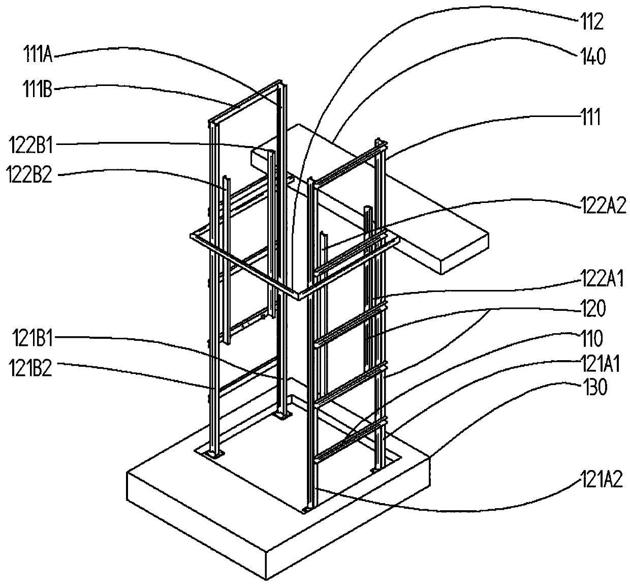
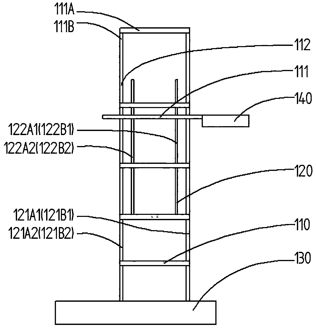
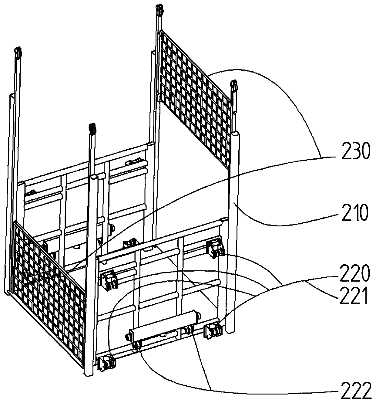
[0048] Such as figure 1 As shown, the lifting device in one embodiment of the present invention includes three parts: a basic frame 100 , a lifting frame 200 and a driv...


PUM


Abstract

The invention relates to a lifting device, in particular for large lifting heights. It has a basic frame, a lifting frame and a driving device. The driving device includes a first hydraulic drive unit and a second hydraulic drive unit arranged symmetrically on the left and right, and several table sensors, which are used to detect whether a certain side of the lifting frame reaches the target. table top; a third hydraulic drive unit is arranged between the lifting frame and the basic frame, and the hydraulic cylinder of the first or second hydraulic drive unit is coaxial or collinear with the hydraulic cylinder of the third hydraulic drive unit; the first The first, second and third hydraulic drive units have the same performance and size. Since the third hydraulic drive unit can perform interchangeable coaxial automatic fine-tuning on the lifting frame when the lifting frame is tilted, the lifting frame can be automatically leveled during multiple round trips without tilting, effectively improving the stability of the lifting frame performance, reliability and applicability.

Description

technical field [0001] The invention relates to a large lifting device / lifting platform, especially suitable for large lifting heights, the lifting device has a basic frame, a lifting frame for receiving the working load and at least one set for positioning the lifting frame relative to the basic frame Vertical lift drive. Background technique [0002] This lifting device is used to lift the working load placed on the lifting frame. For example, in industrial production, the lifting device is used to lift or lower the material to a height of preferably 0.5m or even 20m or more, so that the material leaves the initial platform and reaches the target platform. [0003] Known lifting devices such as those described in PCT / EP2007 / 003519 are mainly suitable for small lifting heights, and cannot be used in applications with large lifting heights. Known lifting devices such as the lifting devices described in CN201120139819.8, etc. are suitable for large lifting heights and large...

Claims


Application Information

Patent Timeline
IPC IPC(8): B66F7/20B66F7/28
CPCB66F7/20B66F7/28
Inventor 黄彬彬吴子剑陈艳
Owner 广东浩翔机械制造有限公司
Why Eureka
Try Eureka