Systems and methods for humidity determination and uses thereof

A technology for relative humidity and sensors, applied in radio wave measurement systems, using sound waves/ultrasonic waves/infrasonic waves for material analysis, using re-radiation, etc., can solve problems such as degradation and sensor blackening

Pending Publication Date: 2018-04-17
FORD GLOBAL TECH LLC
View PDF15 Cites 1 Cited by
  • Summary
  • Abstract
  • Description
  • Claims
  • Application Information

AI Technical Summary

Problems solved by technology

Furthermore, in the case where the exhaust gas oxygen sensor is used for humidity sensing, freq

Method used


Image

  • Systems and methods for humidity determination and uses thereof
  • Systems and methods for humidity determination and uses thereof
  • Systems and methods for humidity determination and uses thereof

Examples


Embodiment Construction

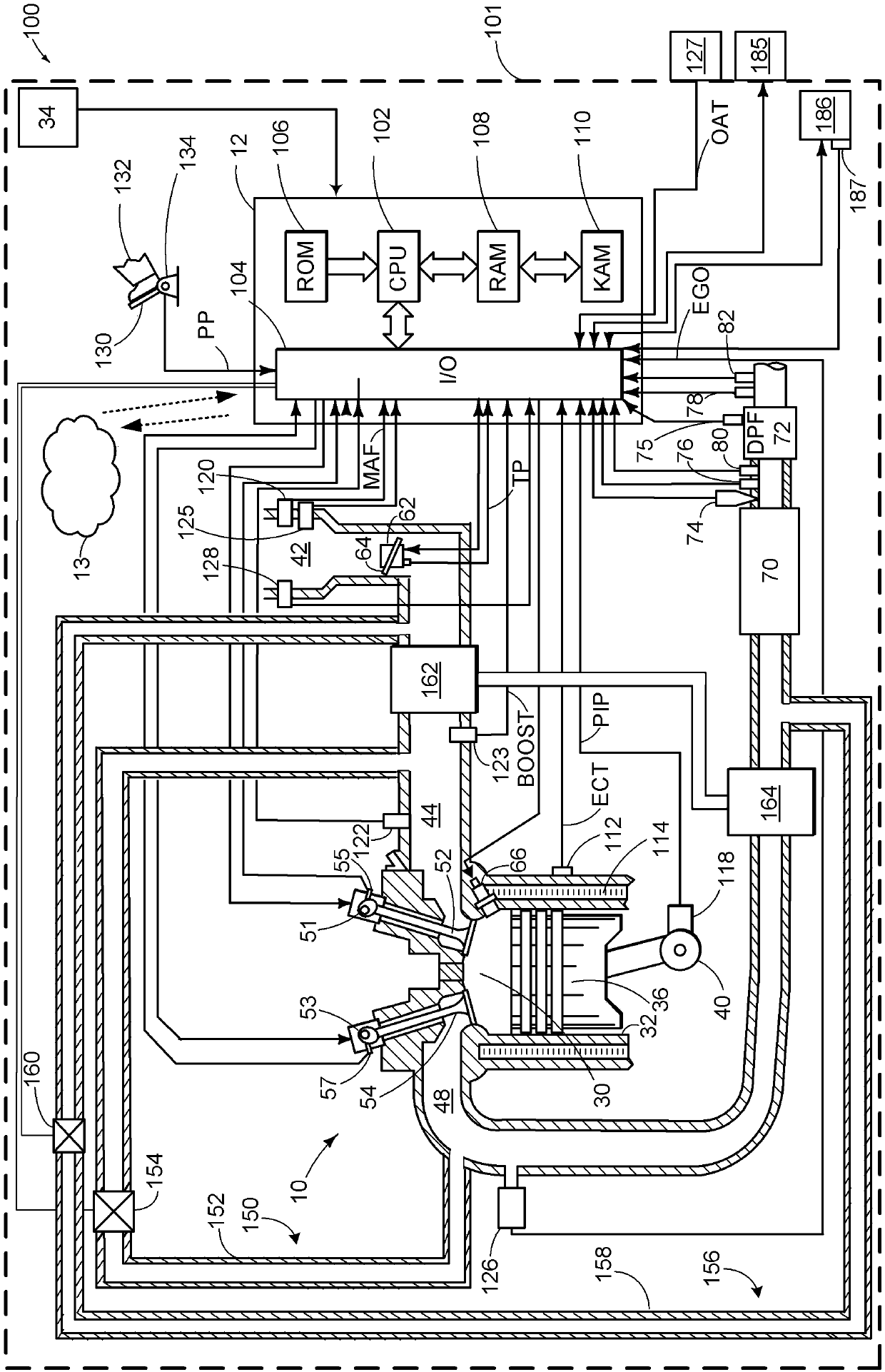
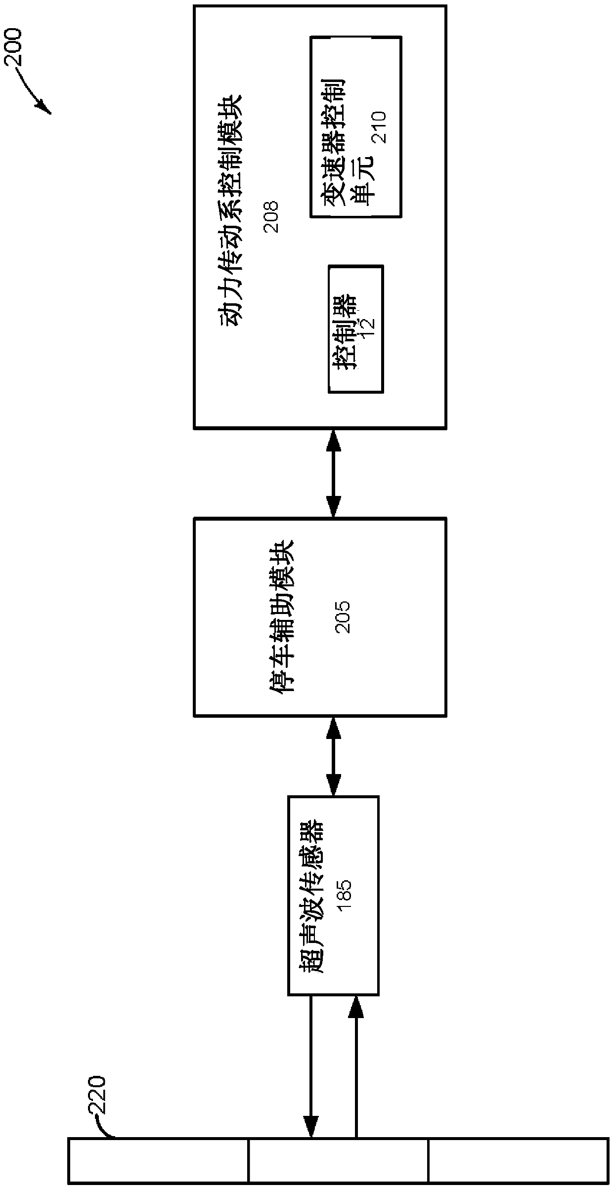
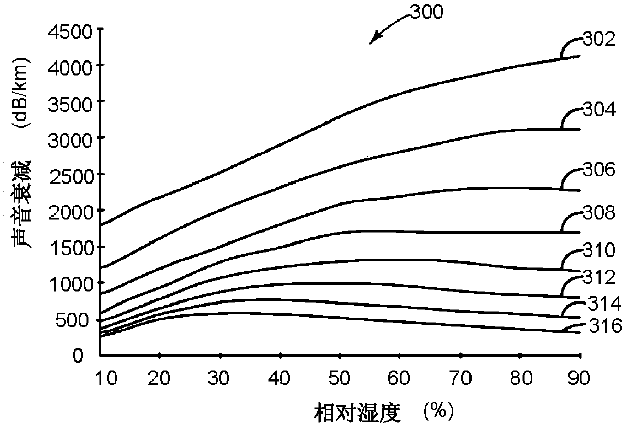
[0028] The following description relates to systems and methods for making relative humidity measurements and adjusting vehicle operating parameters in response to relative humidity determinations. Such measurements can be made by vehicle systems including internal combustion engines such as figure 1 Implementation of the vehicle system depicted in , where the vehicle may be further configured with one or more on-board cameras and one or more ultrasonic sensors. In some examples, the vehicle may be a hybrid vehicle capable of operating for an extended period of time without engine operation. Knowledge of relative humidity can improve the functionality of, for example, assisted or fully automated parking programs that can be accessed via, for example, figure 2 shown in the parking assist system. In some examples, such as Figure 3A As shown, a humidity measurement can be determined via an ultrasonic sensor based on the relationship between sound attenuation, relative humidi...


PUM


Abstract

The invention relates to systems and methods for humidity determination and uses thereof. Methods and systems are provided for conducting measurements of relative humidity via the use of either an ultrasonic sensor positioned on the vehicle, or via another sensor. In one example, responsive to a request for a relative humidity measurement and an indication of fueled engine operation, the ultrasonic sensor may be utilized, whereas responsive to an indication of non-fueled engine operation, another sensor may be utilized. In this way, robust measurement of relative humidity with desired accuracymay be actively determined, rather than opportunistically, and such measurements of relative humidity may be utilized to adjust vehicle operating parameters, which may improve overall vehicle operation.

Description

technical field [0001] The present description generally relates to methods and systems for determining relative humidity via an ultrasonic sensor or other device, and adjusting one or more vehicle operating parameters based on the humidity determination. Background technique [0002] One or more ultrasonic sensors may be mounted on a motor vehicle, such as a hybrid electric vehicle (HEV), to enable distance determination between the sensors and external objects. Such an ultrasonic sensor may consist of at least a piezoelectric disk and a membrane configured to convert electrical energy into mechanical energy and vice versa. More specifically, an oscillating voltage may be applied to the piezoelectric disk so that the piezoelectric disk and the membrane vibrate at a frequency based on the voltage oscillating frequency and generate ultrasonic waves. After the wave is emitted, the sensor waits for an echo to come back from the object / object, and when the echo interacts with t...

Claims


Application Information

Patent Timeline
IPC IPC(8): F02D41/14G01S15/86G01S15/931
CPCF02D41/1444F02D2041/1472G01N29/024G01N29/343G01N29/348G01S15/931G01S7/52004G01S7/52006G01S7/524G01S7/526G01S15/87G01S15/885G01N29/032G01M15/104G01N2291/015G01N2291/02845G01S15/86G01M15/10
Inventor M·麦奎林D·A·马克莱德G·苏妮拉R·E·索尔蒂斯
Owner FORD GLOBAL TECH LLC
Why Eureka
Try Eureka