

Clutch
A clutch device and external friction technology, applied in clutches, power devices, friction clutches, etc., to avoid uncontrollable lubricant backflow and reduce traction torque
- Summary
- Abstract
- Description
- Claims
- Application Information
AI Technical Summary
Problems solved by technology
Method used
Image

Examples
Embodiment Construction
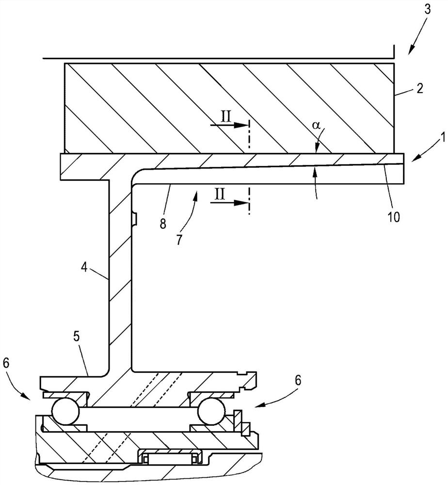
[0023] figure 1 The outer disk carrier 1 according to the invention is shown, in the exemplary embodiment shown, the rotor 2 of the electric machine 3 is connected to the outer disk carrier. As in known solutions, the outer disk carrier 1 is usually part of a known hybrid clutch, which is radially integrated via an annular carrier section 4 and an axially extending bearing section 5 . The position is rotatably supported by the rolling bearing 6.
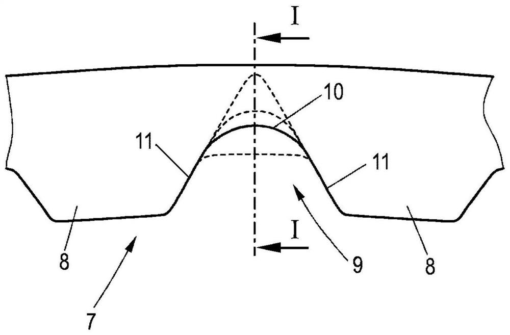
[0024] In known variants, internal toothing 7 is formed on the outer disk carrier 1 , wherein, for the sake of clarity, only the toothing 8 is shown in the sectional view, and not the other toothing rows which are still visible in the sectional view. exist figure 2 The two toothings 8 of the inner toothing 7 are shown in the sectional view along the section line II-II shown in . The teeth 8 are each spaced apart from one another by a groove 9 , wherein the teeth 8 and the grooves 9 extend over the entire length of the outer disk ...
PUM
 Abstract
Description
Claims
Application Information