Hydraulic valve with liquid level being convenient to observe

A liquid level and hydraulic technology, applied in the field of hydraulic valves that are convenient to observe the liquid level, can solve the problems of heavy weight, unsatisfactory, difficult to control water flow, etc., and achieve the effect of strong pressure resistance and weight reduction

Inactive Publication Date: 2018-04-17
温州诚博阀门有限公司
View PDF0 Cites 0 Cited by
  • Summary
  • Abstract
  • Description
  • Claims
  • Application Information

AI Technical Summary

Problems solved by technology

[0003] Due to the defects of the structure of the existing technology in the early stage, it is difficult to observe the water level inside the valve body, and it is difficult to control the water flow when it is used, so it cannot meet the needs of the existing technology.
[0004] In the prior art, the gates of the valves in use have the effect of blocking and sealing, but the weight of the gate itself is too large, which makes it very troublesome to operate, so it cannot meet the requirements of the prior art. need

Method used


Image

  • Hydraulic valve with liquid level being convenient to observe
  • Hydraulic valve with liquid level being convenient to observe

Examples


Embodiment Construction

[0017] The following will clearly and completely describe the technical solutions in the embodiments of the present invention with reference to the accompanying drawings in the embodiments of the present invention. Obviously, the described embodiments are only some, not all, embodiments of the present invention. Based on the embodiments of the present invention, all other embodiments obtained by persons of ordinary skill in the art without making creative efforts belong to the protection scope of the present invention.

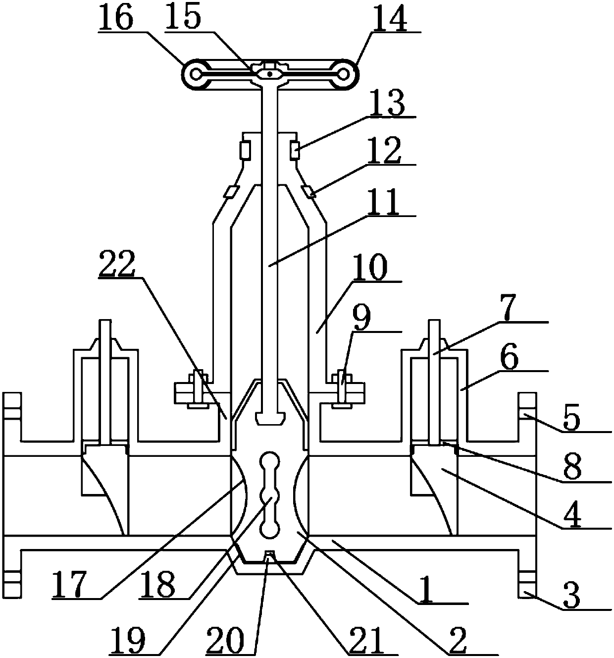
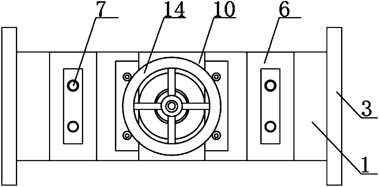
[0018] see Figure 1-2 , the present invention provides a technical solution: a hydraulic valve convenient for observing the liquid level, including a valve body 1, a gate plate 2, a wedge 4, an observation frame 6, a support rod 7, a valve cover 10, a threaded rod 11, and a turntable 14 and valve hole 22, both ends of the valve body 1 are fixedly connected with connecting flanges 3, and the connecting flange 3 is provided with mounting holes 5 near the edge, ...


PUM


Abstract

The invention discloses a hydraulic valve convenient for observing the liquid level, which comprises a valve body, a gate plate, a wedge, an observation frame, a support rod, a valve cover, a threaded rod, a turntable and a valve hole, and both ends of the valve body are fixed There are connecting flanges, and the connecting flanges are provided with mounting holes near the edge, the top of the threaded rod is fixed with a turntable, and the lower end of the threaded rod is threaded with a ram, and the ram is provided with a hole , the middle part of the valve hole is fixedly connected with a sealing plate, the surface of the sealing plate is fixedly connected with a rubber seal ring, and the valve body on both sides of the valve hole is fixedly connected with an observation frame, and the inside of the observation frame is close to the lower The end is sleeved with a wedge, and the upper surface of the wedge is fixed with a support rod, and the top of the support rod runs through the upper surface of the observation frame; through the observation frame fixed on the valve body on both sides of the valve hole, the inside of the observation frame The lower end is connected with a wedge, and the top of the wedge is fixed with support rods on both sides, which makes it easier to observe the water level index on both sides of the valve body during use.

Description

technical field [0001] The invention relates to the technical field of hydraulic valves, in particular to a hydraulic valve for convenient observation of liquid levels. Background technique [0002] The hydraulic control valve is a valve controlled by water pressure. The hydraulic control valve is composed of a main valve and its attached conduit, pilot valve, needle valve, ball valve and pressure gauge. According to different purposes, functions and places, it can be evolved into remote control float valve, pressure reducing valve, slow closing check valve, flow control valve, pressure relief valve, hydraulic electric control valve, water pump control valve, etc. A filter should be installed before the hydraulic control valve, and it should be convenient for sewage discharge. This type of valve should generally be installed horizontally in the pipeline. The prior art has many defects such as: [0003] Due to the defects of the structure of the existing technology in the ...

Claims


Application Information

Patent Timeline
Patent Type & Authority Applications(China)
IPC IPC(8): F16K3/02F16K3/314F16K37/00
CPCF16K3/02F16K3/314F16K37/0008
Inventor 林列谦
Owner 温州诚博阀门有限公司
Why Eureka
Try Eureka