SOC chip and radio-frequency signal processing method

A radio frequency signal and chip technology, which is applied in data processing power supply, data processing applications, electrical digital data processing, etc., can solve the problems of high power consumption of radio frequency chips and poor user experience, and achieve the effect of reducing power consumption

Pending Publication Date: 2018-04-17
SHANGHAI QUANRAY ELECTRONICS
View PDF0 Cites 7 Cited by
  • Summary
  • Abstract
  • Description
  • Claims
  • Application Information

AI Technical Summary

Problems solved by technology

[0003] However, when the RF front-end chip is installed in the smart terminal, as the complexity of the application environment increases, in order to meet the payment requirements of the RF chip, an operati

Method used


Image

  • SOC chip and radio-frequency signal processing method
  • SOC chip and radio-frequency signal processing method
  • SOC chip and radio-frequency signal processing method

Examples


Embodiment 1

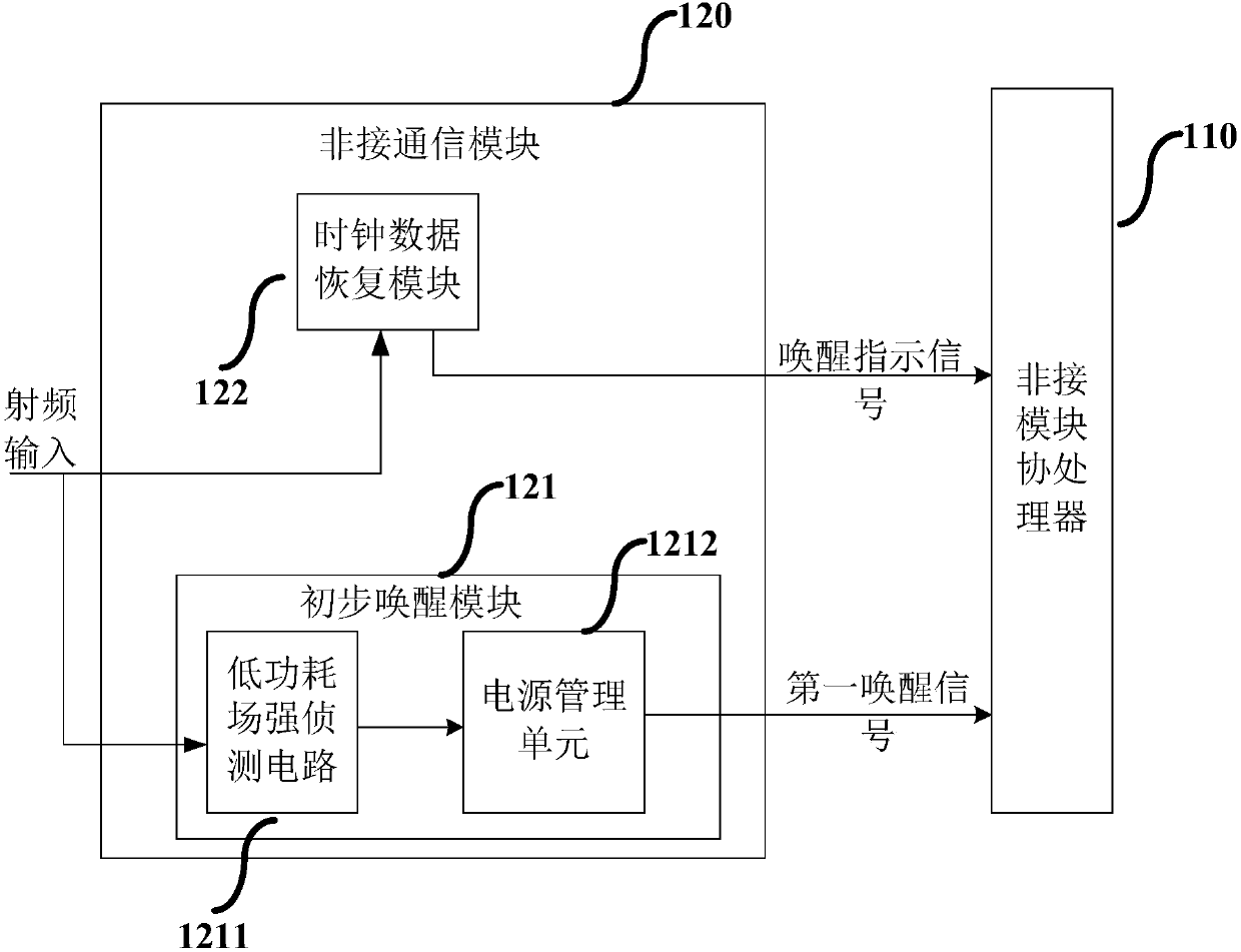
[0023] figure 1 It is a schematic structural diagram of a SOC chip provided by Embodiment 1 of the present invention. The SOC chip can be integrated into a smart terminal such as a smart phone, a bracelet or a smart watch, and used as a radio frequency analog tag to realize a safe and reliable NFC (Near Field Communication, near field communication) payment function.

[0024] see figure 1 , the SOC (System on Chip, system-on-chip) chip specifically includes: a contactless module coprocessor 110 and a contactless communication module 120 .

[0025] The contactless communication module 120 is electrically connected to the contactless module coprocessor 110, including a preliminary wake-up module 121 and a clock data recovery module 122;

[0026] The preliminary wake-up module 121 is electrically connected with the contactless module coprocessor 110, and is used to detect the field strength of the radio frequency field where the SOC chip is located, and when detecting that the ...

Embodiment 2

[0094] Figure 4 It is a flowchart of a radio frequency signal processing method provided by Embodiment 2 of the present invention. This embodiment is applicable to the case where the SOC chip in the smart terminal processes radio frequency signals, and the method can be executed by the SOC chip provided by the embodiment of the present invention. Specifically include the following steps:

[0095] S210. Acquire an input radio frequency signal, and acquire the signal strength of the input radio frequency signal.

[0096] In this embodiment, the field strength of the radio frequency field where the SOC chip is located is represented by the signal strength of the input radio frequency signal.

[0097] S220. If it is detected that the signal strength is greater than a preset value, generate a first wake-up instruction, and power on the SOC chip according to the first wake-up instruction.

[0098] Wherein, if the detected signal strength is greater than the preset value, it indic...


PUM


Abstract

The invention discloses an SOC chip and a radio-frequency signal processing method. The SOC chip comprises a non-contact module coprocessor and a non-contact communication module; the non-contact communication module is electrically connected with the non-contact module coprocessor and comprises a primary arousing module and a clock data recovery module; the primary arousing module is electricallyconnected with the non-contact module coprocessor and used for detecting the field intensity of a radio-frequency field where the SOC chip is and sending a first arousing instruction to the non-contact module coprocessor when detecting that the field intensity is greater than a preset value; the non-contact module coprocessor is electrically connected with the clock data recovery module; the clock data recovery module is used for entering a working state according to the first arousing instruction, extracting a clock signal of an input radio-frequency signal and sending an arousing indicationsignal to the non-contact module coprocessor according to the clock signal; and the non-contact module coprocessor is further used for determining whether the SOC chip is aroused or not according tothe arousing indication signal. The power consumption of the SOC chip is reduced.

Description

technical field [0001] Embodiments of the present invention relate to wireless communication technologies, and in particular to an SOC chip and a radio frequency signal processing method. Background technique [0002] With the continuous development of wireless communication technology, NFC (Near Field Communication, near field communication) payment methods are more and more widely used, and NFC front-end chips are integrated into smart terminals such as smartphones and smart bracelets, making smart The terminal has functions such as NFC payment, which improves the convenience of user payment. [0003] However, when the RF front-end chip is installed in the smart terminal, as the complexity of the application environment increases, in order to meet the payment requirements of the RF chip, an operating system is added to the RF chip to cooperate with the host to run. However, due to the increase in the operating system, etc., As a result, the power consumption of the radio ...

Claims


Application Information

Patent Timeline
IPC IPC(8): G06F15/78G06F1/32G06Q20/32H04W4/80H04W52/02
CPCH04W52/0229G06F1/329G06F15/7817G06Q20/3278Y02D10/00Y02D30/70
Inventor 沈仲汉佘磊任文亮
Owner SHANGHAI QUANRAY ELECTRONICS
Why Eureka
Try Eureka