Electronically controlled pneumatic braking system in a commercial vehicle, and method for electronically controlling a pneumatic braking system

A brake system and electronic control technology, applied in the direction of brake control system, brake safety system, ABS control system, etc., can solve the problem that the control valve does not have a backup solution that can be electronically controlled

Active Publication Date: 2018-04-17
ZF CV SYST EURO BV
View PDF15 Cites 10 Cited by
  • Summary
  • Abstract
  • Description
  • Claims
  • Application Information

AI Technical Summary

Problems solved by technology

[0003] In the prior solutions of known vehicles with a pneumatic braking system, it is a disadvantage that there is no electronically controllable backup in the event of an electronically actuated control valve failing.

Method used


Image

  • Electronically controlled pneumatic braking system in a commercial vehicle, and method for electronically controlling a pneumatic braking system
  • Electronically controlled pneumatic braking system in a commercial vehicle, and method for electronically controlling a pneumatic braking system
  • Electronically controlled pneumatic braking system in a commercial vehicle, and method for electronically controlling a pneumatic braking system

Examples


Embodiment Construction

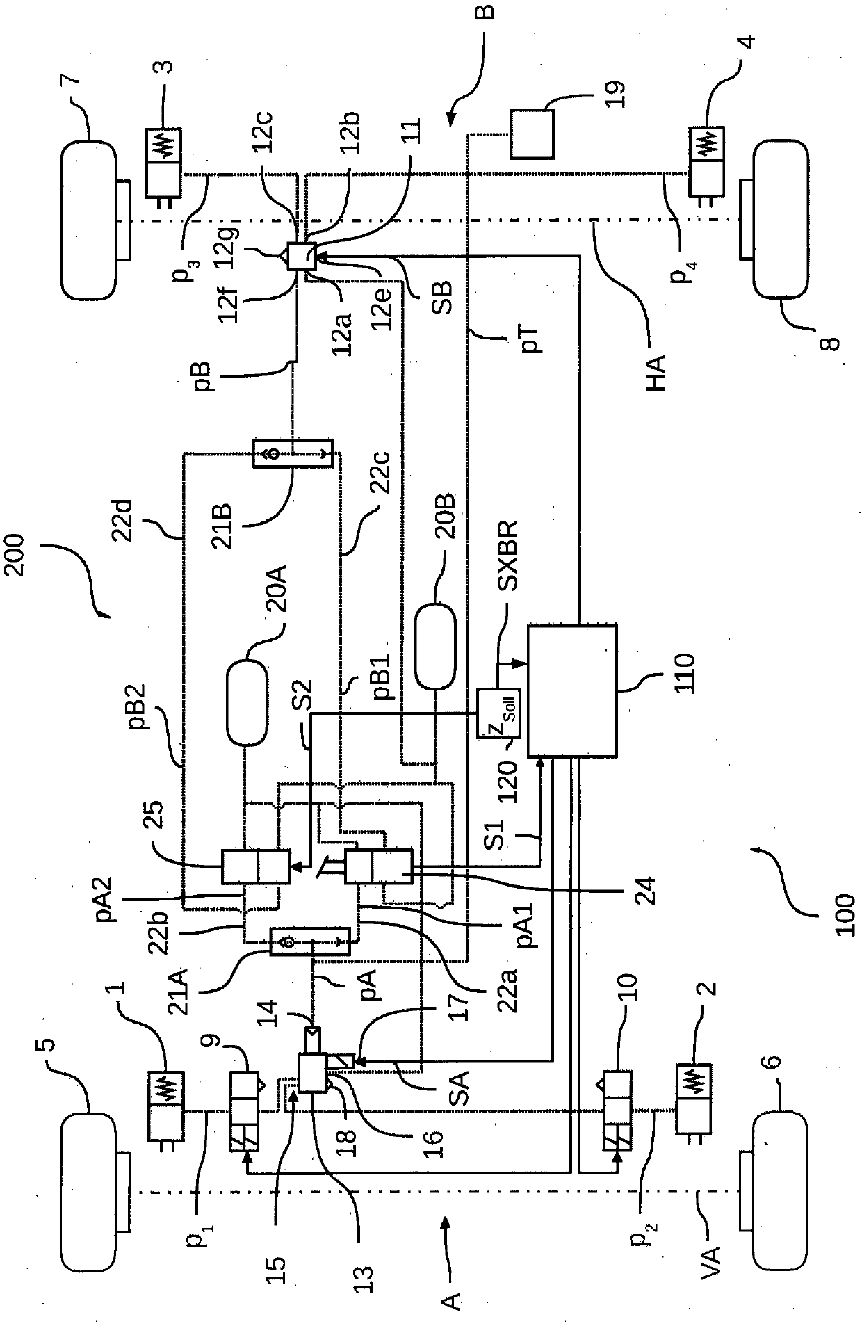
[0046] according to Figure 1a The specific embodiment relates to an electronically controlled pneumatic braking system 100 in a commercial vehicle 200 having service brakes 1 , 2 , 3 , 4 on wheels 5 , 6 , 7 , 8 . On the wheels 5 , 6 of the front axle VA, respectively, conventional ABS brake valves 9 , 10 are arranged upstream of the service brakes 1 , 2 and serve to regulate the brake pressure p1 , p2 depending on the detected ABS slippage. On the drive wheels 7 , 8 of the rear axle HA, according to the present embodiment, upstream of the service brakes 3 , 4 are arranged axle modulators 11 , which can be supplied electronically and pneumatically to the respective service brakes 3 , 4 in a known manner. brake pressure p3, p4, and the slippage of the rear wheels 7, 8 can be taken into account here. The axle modulator 11 and the ABS brake valves 9 , 10 are electronically controlled by a first control unit 110 . However, separate control units can also be provided for the axle ...


PUM


Abstract

The invention relates to an electronically controlled pneumatic braking system (100) comprising at least one braking circuit (A, B) with which at least one control valve (13, 11) for adjusting brakingpressures (p1, p2, p3, p4) is associated, the at least one control valve (13, 11) being controllable electronically in accordance with a control signal (SA, SB) and pneumatically in accordance with acontrol pressure (pA, pB). According to the invention, a second brake valve (25) is provided in addition to a first brake valve (24), the second brake valve (25) being able to output a pneumatic second brake valve control pressure (pA2, pB2) in an electronically controlled manner. The first brake valve (24) can, in addition to an actuation signal (S1), pneumatically output a first brake valve control pressure (pA1, pB1). The two brake valves (24, 25) are disposed in the pneumatic braking system (100) in such a way that the first brake valve control pressure (pA1, pB1) of the first brake valve(24) and/or the second brake valve control pressure (pA2, pB2) of the second brake valve (25) is/are output as the control pressure (pA, pB) to the at least one control valve (13, 11) in order for the at least one control valve (13, 11) to be pneumatically controlled, and the second brake valve (25) can be electronically controlled when the at least one control valve (11, 13) is prevented from being electrically controlled, such that an electronically-pneumatically controlled redundancy is created.

Description

technical field [0001] The invention relates to an electronically controllable braking system in a commercial vehicle, in particular an autonomously controllable commercial vehicle, and to a method for electronically controlling a pneumatic braking system. Background technique [0002] In vehicles, in particular commercial vehicles, with a pneumatic braking system, in particular configured as an electronic braking system (EBS) or an anti-lock braking system (ABS), the control unit (ECU) is actuated to provide brake pressure Electronically controlled valves, such as relay valves or axle modulators, which transmit brake pressure pneumatically to the brake cylinders of the service brakes of the braking system, depending on the required target deceleration of the vehicle. The provision of the brake pressure is based on the operation of the brake force regulator or the brake value encoder of the driver's operation of the brake pedal. Perform emergency braking and / or override ele...

Claims


Application Information

Patent Timeline
Patent Type & Authority Applications(China)
IPC IPC(8): B60T13/66B60T13/68B60T17/18
CPCB60T13/662B60T13/683B60T17/18B60T7/042B60T7/12B60T8/17B60T8/1708B60T8/176B60T13/26B60T15/027B60T2270/10B60T2270/402B60T2270/413B60T2270/82
Inventor 罗伯特·奥特伦巴
Owner ZF CV SYST EURO BV
Why Eureka
Try Eureka