Electric pump and method for producing same

An electric pump and motor technology, applied in the direction of pumps, rotary piston type/swing piston type pump parts, pump components, etc., to achieve the effect of improving filling and reducing flow resistance

Active Publication Date: 2018-04-17
AISIN SEIKI KK
View PDF10 Cites 5 Cited by
  • Summary
  • Abstract
  • Description
  • Claims
  • Application Information

AI Technical Summary

Problems solved by technology

In reality, there is no perfect concen...

Method used


Image

  • Electric pump and method for producing same
  • Electric pump and method for producing same
  • Electric pump and method for producing same

Examples


Embodiment Construction

[0030] Hereinafter, embodiments of the present invention will be described in detail using the drawings.

[0031] 1. Structure and action of electric pump

[0032] [the whole frame]

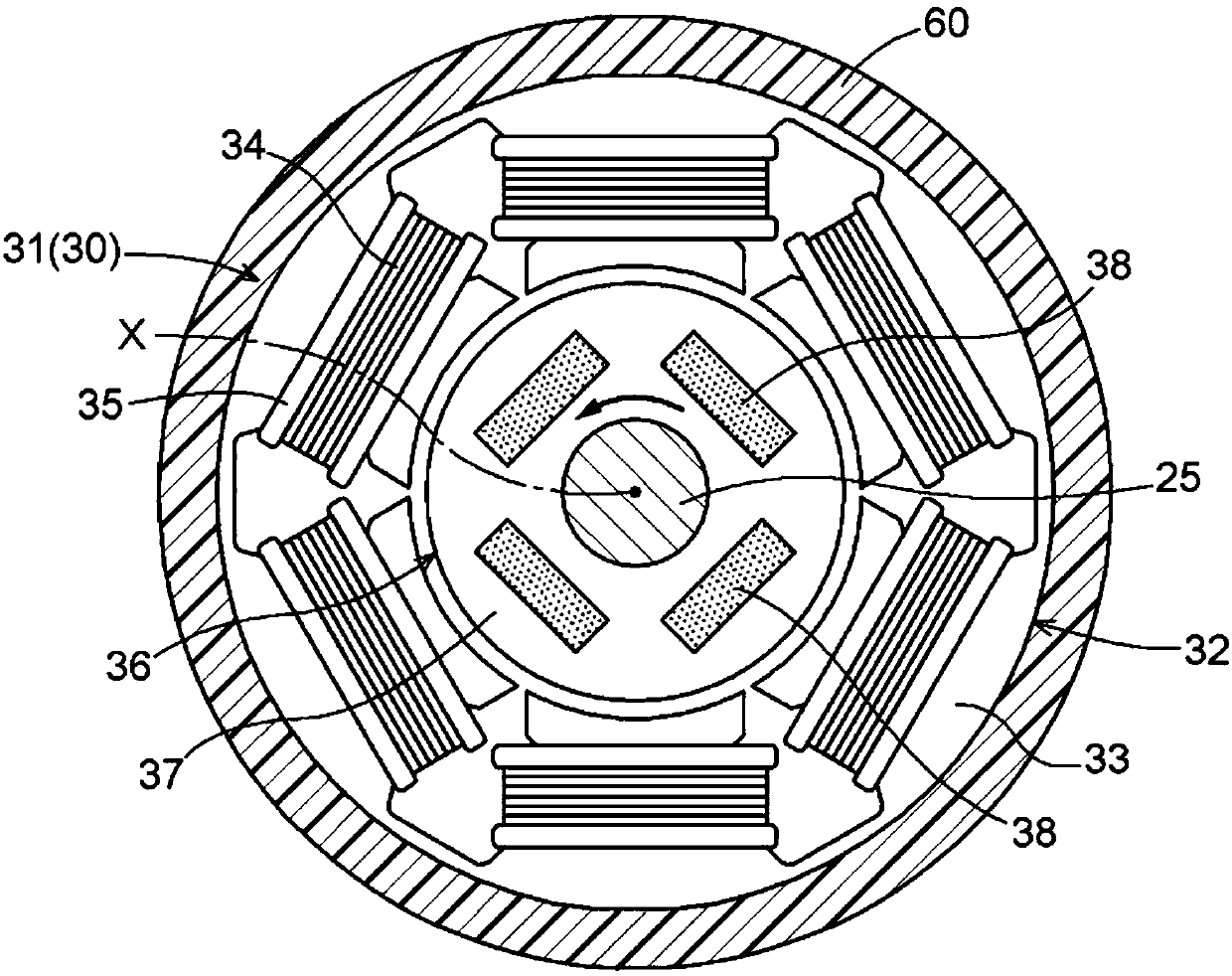
[0033] Such as Figure 1 ~ Figure 3 As shown, the electric pump 1 is composed of a motor part 30, a pump part 10, a control part 50, and a resin part 60. 30 across to the pump parts 10 and formed on their outer peripheries. Although the electric pump 1 is used to pressure-pump lubricating oil of an engine of a vehicle as working oil to a hydraulic machine, it can also be used in a hydraulic device other than a vehicle. In addition, liquid chemicals or chemical substances may be used as pressure pumping objects instead of working oil. It should be noted that working oil is an example of working fluid.

[0034] [Structure of pump part]

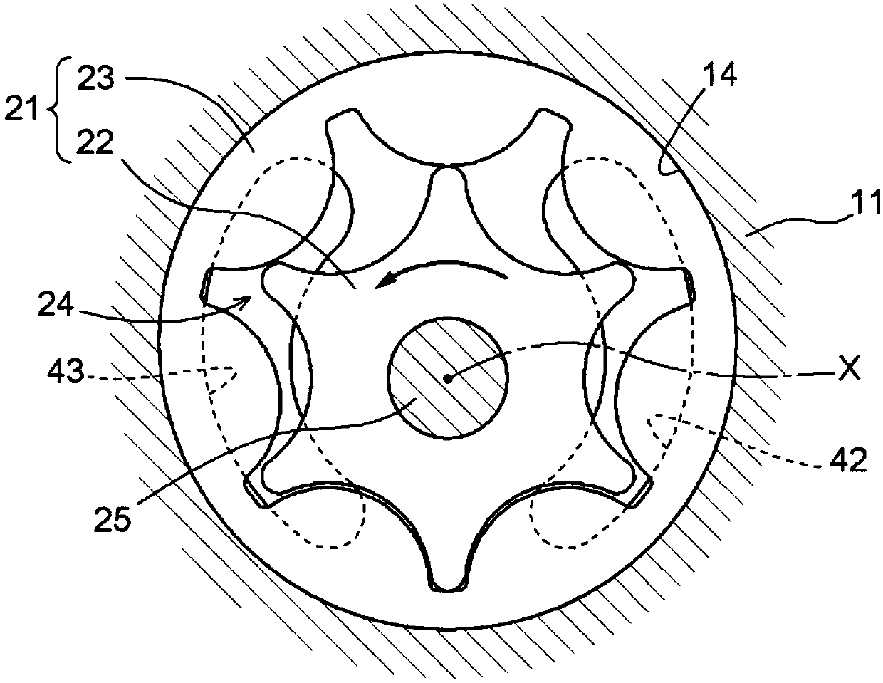
[0035] Such as figure 1 As shown, the pump unit 10 includes a pump casing 11 , an internal meshing gear pump 21 and a pump cover 40 . It should be noted th...


PUM


Abstract

Provided is an electric pump comprising a pump unit that has a pump housing and a gear pump accommodated in the pump housing and that suctions in and discharges a working fluid due to rotation of thegear pump. The electric pump is also provided with a motor unit that has a rotor which is arranged adjacent to the pump unit in a direction along the axis of the pump unit and which rotates coaxiallywith the axis and synchronously with the gear pump, and a stator which is disposed coaxially with the axis on the outer periphery of the rotor and which imparts rotational driving force to the rotor.The electric pump is further provided with a resin part integrally covering at least the outer periphery of the pump housing and the outer periphery of the stator.

Description

technical field [0001] The invention relates to an electric pump and a manufacturing method thereof. Background technique [0002] The electric pump is used for supplying working fluid to various movable mechanisms of vehicles, for example. The electric pump includes a motor unit and a pump unit. When the electric pump is operated, the rotational driving force of the rotating shaft of the motor unit is transmitted to the gear pump of the pump unit, and the gear pump is rotated to suck and discharge the working fluid. [0003] Usually, the motor part and the pump part of the electric pump are manufactured separately and then assembled so that the offset between the axis of the motor part and the axis of the pump part is reduced as much as possible, that is, the offset between the two axes is minimized. The degree of concentricity is reduced as much as possible. In reality, there is no perfect concentricity in which the coaxiality of the two axes is zero. However, in order...

Claims


Application Information

Patent Timeline
IPC IPC(8): F04C2/10F04C15/00
CPCF04C15/00F04C2/086F04C2/18F04C2/10F04C15/008F04C2230/21
Inventor 安藤辉哉永田健次郎岩濑昌吾
Owner AISIN SEIKI KK
Why Eureka
Try Eureka