Internal cleaning system of dedusting pipeline

A cleaning system and pipeline technology, applied in the field of mechanical equipment, can solve the problems of affecting the dust removal effect of the dust removal pipeline, the dust removal pipeline is easy to consolidate and adhere to block dust, and it is difficult to remove block dust, so as to reduce the workload of operation and maintenance and ensure Airtightness and the effect of reducing maintenance costs

Inactive Publication Date: 2018-04-20
BAOSTEEL ENG & TECH GRP
View PDF6 Cites 8 Cited by
  • Summary
  • Abstract
  • Description
  • Claims
  • Application Information

AI Technical Summary

Problems solved by technology

[0006] The purpose of the present invention is to provide a cleaning system inside the dust removal pipeline, which can timely process the dust in the dust removal pipeline, so as to solve the problem that the existing dust removal pipeline is easy to consolidate and adhere to the block dust, and it is difficult to remove the block dust by conventional means , a technical problem that will affect the dust removal effect of the dust removal pipeline for a long time

Method used


Image

  • Internal cleaning system of dedusting pipeline
  • Internal cleaning system of dedusting pipeline
  • Internal cleaning system of dedusting pipeline

Examples


Embodiment 1

[0034] This embodiment discloses a system for cleaning the interior of the dust removal pipeline, which cleans the dust inside the dust removal pipeline 1. The dust removal pipeline 1 is the dust transmission pipeline in the dust removal system, and the dust removal system is stainless steel slag processing, etc. Dust treatment method, dust removal equipment used in the device.

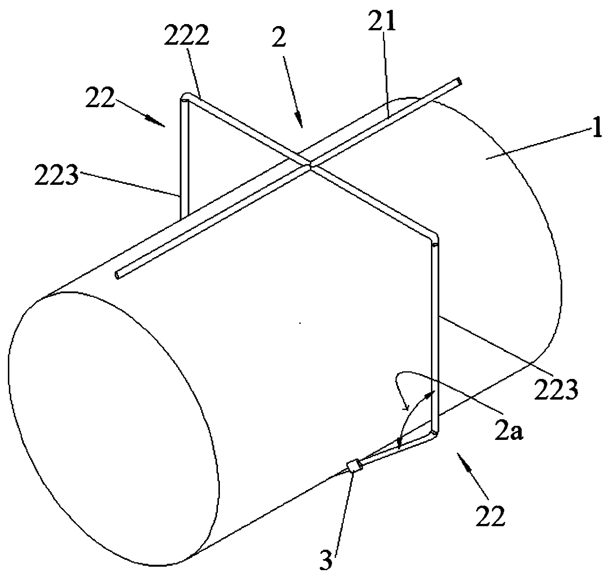
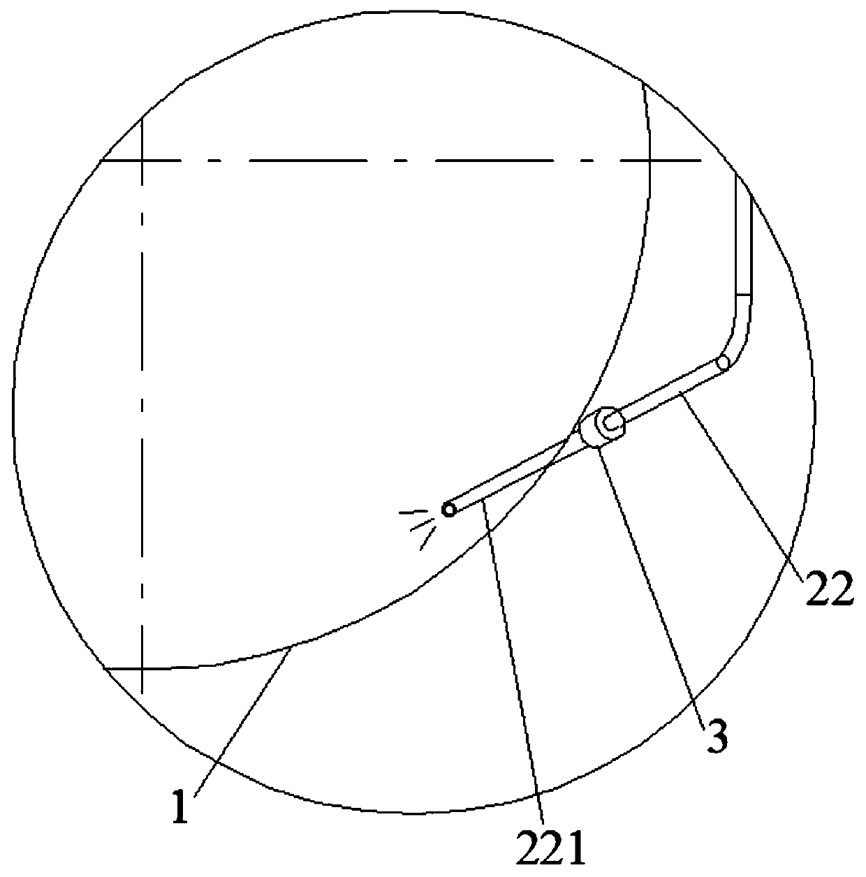
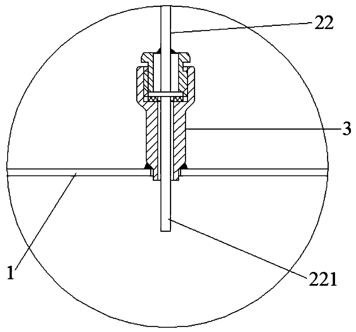
[0035] Please refer to figure 1 , is a structural schematic diagram of a blowing unit in the dust removal pipeline internal cleaning system provided by the present invention, wherein a dust removal pipeline internal cleaning system includes at least one blowing unit 2 distributed on the dust removal pipeline 1; the blowing unit 2 is connected to A high-pressure air source, wherein the blowing unit includes at least one blowing nozzle 221 , and the blowing nozzle 221 of the blowing unit 2 passes through the pipe wall of the dust removal pipeline 1 and enters the inside of the dust removal pipeline 1 . ...

Embodiment 2

[0056] This embodiment is described based on the content of Embodiment 1, therefore, similar components are denoted by similar reference numerals.

[0057] Such as Figure 4 As shown, the difference between this embodiment and Embodiment 1 is that the cleaning system includes three sets of blowing units 2, and the three sets of blowing units 2 are separated along the extension of the dust removal pipeline 1 according to a certain distance. The direction is distributed on the dust removal pipeline 1, and the distance between the adjacent spray units 2 can be set according to the length of the dust removal pipeline 1, for example, in the middle of the dust removal pipeline 1, a The above-mentioned blowing unit starts from the middle part of the dust removal pipeline 1, extends to both ends for a certain distance, and then installs the remaining two groups of blowing units 2, so that the three sets of blowing units 2 can cover the dust removal pipeline to avoid cleaning. out of ...


PUM


Abstract

The invention relates to the technical field of mechanical equipment, in particular to an internal cleaning system capable of treating dust in a dedusting pipeline timely. The internal cleaning systemcomprises at least one blowing unit which is arranged on the dedusting pipeline; the blowing unit is connected with a high-pressure air source; the blowing unit comprises at least one blowing nozzle;and the blowing nozzle penetrates through the pipe wall of the dedusting pipeline and is arranged in the dedusting pipeline. By adopting the internal dedusting system of the dedusting pipeline, the dust in the dedusting pipeline can be cleaned when the dedusting pipeline stops working, so that the problem that the dust in the dedusting pipeline is adhered and solidified into bulks which are difficult to clean, and the dedusting effect is low is solved; the operation maintenance workload of the dedusting pipeline can be reduced; the maintenance cost of the dedusting pipeline is lowered; energyis saved; the environment is protected; and the internal cleaning system is safe and reliable.

Description

technical field [0001] The invention relates to the technical field of mechanical equipment, in particular to an internal cleaning device capable of timely processing the dust in a dust removal pipeline. Background technique [0002] During the slag dumping process of the stainless steel slag treatment process, a large amount of dust with high humidity will be generated. The dust is collected by the pipeline system and enters the dust removal system. The commonly used dust removal system is the plastic burning plate dust removal system. [0003] The slag treatment process carried out by the above system, due to its technological requirements, adopts the discontinuous operation method to implement dust treatment. The dust removal pipe in the dust removal system is usually a carbon steel pipe. When the dust removal system stops running, a large amount of water vapor accumulated in the dust removal pipe will slowly condense into liquid water droplets as the ambient temperatu...

Claims


Application Information

Patent Timeline
Patent Type & Authority Applications(China)
IPC IPC(8): B08B9/032
CPCB08B9/0328
Inventor 张佳君徐杰吴碧容张挺峰
Owner BAOSTEEL ENG & TECH GRP
Why Eureka
Try Eureka