
Method of holographic perception and layered line loss calculation

A holographic and line loss technology, applied in the direction of AC network circuits, electrical components, circuit devices, etc., can solve the problems of meterless electricity stealing, damage to metering box locks, etc.

Inactive Publication Date: 2019-08-20
CHANGCHUN POWER SUPPLY COMPANY OF STATE GRID JILINSHENG ELECTRIC POWER SUPPLY
View PDF5 Cites 7 Cited by
  • Summary
  • Abstract
  • Description
  • Claims
  • Application Information

AI Technical Summary

Problems solved by technology

[0002] Based on the ubiquitous power Internet of Things technology, the innovative application in the field of power loss reduction and intelligent anti-stealing in the power system, in the power system, the power supply area refers to the power supply range or area of ​​(one) transformer, which is the basis of power economic operation management Nouns, and in specific sentences, it is a place name of a region. The station area mostly includes regional power supply lines, substations, meter boxes and electric energy meter lamps, but existing power supply lines, station substations, meter boxes, and electric energy meters in some areas Correspondence files are inaccurate, metering box locks are seriously damaged by man-made external forces, power consumption without meters, and power theft outside meters are prominent. Most of the meters are version 2009 and 2013, and a small part of them have ERR-04 (battery undervoltage) alarms , here, the calculation of intelligent holographic perception and layered line loss of the power grid at the end of the station area is also of great importance

Method used


Image

  • Method of holographic perception and layered line loss calculation
  • Method of holographic perception and layered line loss calculation

Examples


Embodiment 1

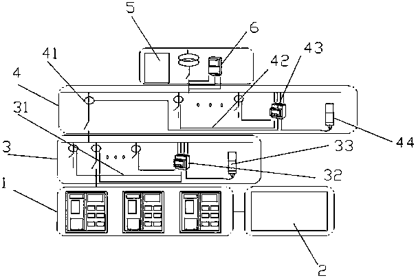
[0027] A method for holographic perception and layered line loss calculation in the ubiquitous Internet of Things digital station area, including a metering box 1, a digital terminal 2, a branch box 3, a JP cabinet 4, a transformer 5 and a new concentrator 6, the metering box 1 is docked with the digital terminal 2 through a cable, and the digital terminal 2 is installed in the metering box 1, and the metering box 1 is electrically connected with the branch box 3 through the cable, and the branch box 3 is connected with the JP cabinet 4, and the JP The cabinet 4 is connected with the transformer 5 and the new concentrator 6 respectively, and the new concentrator 6 is installed in the JP cabinet 4 .

[0028] The branch box 3 includes a current collection line A31, a metering module A32 and a type II collection module A33, the current collection line A31 is installed in the branch box 3, the current collection line A31 is connected with the metering module A32, and the metering m...

Embodiment 2

[0037] A method for holographic perception and layered line loss calculation in a ubiquitous digital platform of the Internet of Things, the method steps are as follows:

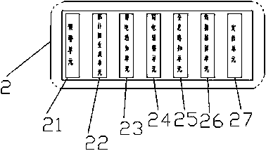
[0038] S1. According to the holographic sensing unit 25 in the digital terminal 2, the data collection and analysis of the event that the voltage value of the electric meter in the metering box 1 exceeds the upper and lower limits;

[0039] S2. The holographic sensing unit 25 sends an instruction to collect and analyze the power factor data in the meter;

[0040] S3, record the voltage and current harmonics of the meter in the metering box 1, and the excessive frequency deviation data, and collect and analyze it;

[0041] S4. After analyzing the full amount of data collected in steps S1-S4, the digital terminal 2 is connected to the network to transmit real-time data on the power quality of the terminal power grid to realize real-time monitoring and early warning of power quality in the station area;

[004...


PUM


Abstract

The invention discloses a method of holographic perception and layered line loss calculation for a ubiquitous Internet of Things transformer area, which comprises a metering box, a digital terminal, abranch box, a JP cabinet, a transformer and a novel concentrator, wherein the digital terminal is installed in the metering box, the novel concentrator is installed in the JP cabinet, and the novel concentrator has an extended function. The method focuses on solving the intelligent perception for power failure and recovery event reporting, line aging early-warning, electric energy meter inaccuracy alarming and suspected electricity stealing early-warning events through real-time measurement and calculation of an electric energy meter, the metering box and a branch line by being matched with each unit in the digital terminal, and can solve the problem of line loss of the low-voltage transformer area in an omni-directional and systematical manner at the same time, thereby achieving the significant improvement of economic benefits on five aspects of preventing electricity stealing, saving the energy and reducing the consumption, prolonging the service life of the electric energy meter, reducing the equipment investment and reducing the operation and maintenance workload.

Description

technical field [0001] The invention relates to the field of station area construction, in particular to a method for holographic perception and layered line loss calculation of ubiquitous Internet of Things digital station areas. Background technique [0002] Based on the ubiquitous power Internet of Things technology, the innovative application in the field of power loss reduction and intelligent anti-stealing in the power system, in the power system, the power supply area refers to the power supply range or area of ​​(one) transformer, which is the basis of power economic operation management Nouns, and in specific sentences, it is a place name of a region. The station area mostly includes regional power supply lines, substations, meter boxes and electric energy meter lamps, but existing power supply lines, station substations, meter boxes, and electric energy meters in some areas Correspondence files are inaccurate, metering box locks are seriously damaged by man-made ex...

Claims


Application Information

Patent Timeline
IPC IPC(8): H02J3/00
CPCH02J3/00H02J2203/20
Inventor 周建曹华彬罗国通许宁赵寰宇宫国亮
Owner CHANGCHUN POWER SUPPLY COMPANY OF STATE GRID JILINSHENG ELECTRIC POWER SUPPLY
Learn More