Clamping centring clamp adopted on shock absorber oil storage cylinder conveying line
A technology of clamping, centering, and oil storage cylinder, which is applied in metal processing and other directions to ensure stability and accuracy, good clamping effect, and reduce production costs.
- Summary
- Abstract
- Description
- Claims
- Application Information
AI Technical Summary
Problems solved by technology
Method used
Image
Examples
Embodiment 1
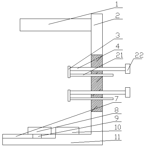
[0026] Embodiment 1, the present invention provides a clamping and centering fixture used on the transmission line of the shock absorber oil storage cylinder, including a bottom plate 11, a bottom fixing mechanism is set in the middle of the bottom plate 11, and a vertical plate is set on one side of the bottom plate 11 2. The middle part of the vertical plate 2 is provided with a positioning mechanism, the upper part of the bottom plate 11 is provided with a clamping mechanism 1, and the bottom plate 11 is fixedly arranged on the transmission line, and the positioning mechanism includes Two telescopic mechanisms, the two telescopic mechanisms are located on the central symmetry line of the vertical plate 2, the end of the telescopic mechanism is provided with a baffle 3, and the telescopic mechanism includes a rotating connection with the baffle 3 The screw 4 is provided with a rotating handle 22 passing through the vertical plate 2, and a guide rod 21 passing through the vert...
Embodiment 2
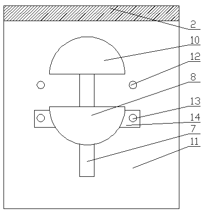
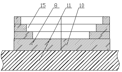
[0028] The difference between the second embodiment and the first embodiment is that the bottom fixing mechanism includes a semicircular first fixing plate 10 set on the bottom plate 11 and a first fixing plate 10 which is movably arranged on the bottom plate 11 and connected with the first fixing plate 10 Matching semicircular second fixing plate 8 .
[0029] A chute 7 is set on the bottom plate 11, a slide block 9 matched with the chute 7 is set below the second fixed plate 8, connecting plates 14 are arranged on both sides of the second fixed plate 8, and the connecting plate 14 is provided with a first threaded hole 13 , and the bottom plate 11 is provided with a second threaded hole 12 , corresponding to the first threaded hole 13 and the second threaded hole 12 are provided with fixing bolts.
[0030] The edges of the first fixing plate 10 and the second fixing plate 8 are provided with multi-stage bosses.
[0031] The bottom fixing mechanism includes a semicircular fir...
Embodiment 3
[0034] Embodiment 3, the difference from Embodiment 1 is that the clamping mechanism 1 includes a first clamping arm 20 and a second clamping arm 17 that are co-located on the upper part of the vertical plate 2, and the first clamping arm 20 and the second clamping arm 20 are One end of clamping arm 17 is connected by spring 16, and the center of described first clamping arm 20 and second clamping arm 17 and the center of described first fixing plate 10 and the center of second fixing plate 8 form the straight line that is perpendicular to described bottom plate 11 .
[0035] An elastic clip body 18 is arranged inside the first clip arm 20 and the second clip arm 17, and the elastic clip body 18 is made of rubber.
[0036] The inner side of the elastic clip body 18 is provided with an arc-shaped groove 19, and the diameter of the circle where the arc-shaped surface of the arc-shaped groove 19 is located is larger than the diameter of the clamped shock absorber oil storage cyli...
PUM
 Abstract
Description
Claims
Application Information
 - R&D Engineer
- R&D Manager
- IP Professional
- Industry Leading Data Capabilities
- Powerful AI technology
- Patent DNA Extraction
Browse by: Latest US Patents, China's latest patents, Technical Efficacy Thesaurus, Application Domain, Technology Topic, Popular Technical Reports.
© 2024 PatSnap. All rights reserved.Legal|Privacy policy|Modern Slavery Act Transparency Statement|Sitemap|About US| Contact US: help@patsnap.com


