Deburring equipment for stainless steel plate for power distribution cabinet production

A deburring, stainless steel technology, applied in metal processing equipment, grinding/polishing equipment, grinding slides, etc., can solve the problems of high production cost, cumbersome operation, poor deburring effect, etc., and achieve good deburring effect. Effect

Inactive Publication Date: 2018-04-20
郭昌磊
View PDF6 Cites 7 Cited by
  • Summary
  • Abstract
  • Description
  • Claims
  • Application Information

AI Technical Summary

Problems solved by technology

[0006] In order to overcome the shortcomings of the existing stainless steel plate deburring equipment, such as high production cost, poor deburring effect and cumbersome operation, the technical problem to be solved by the present invention is to provide a deburring equipment with low production cost, good deburring effect and simple operation. Stainless steel plate deburring equipment for power distribution cabinet production

Method used


Image

  • Deburring equipment for stainless steel plate for power distribution cabinet production
  • Deburring equipment for stainless steel plate for power distribution cabinet production
  • Deburring equipment for stainless steel plate for power distribution cabinet production

Examples


Embodiment 1

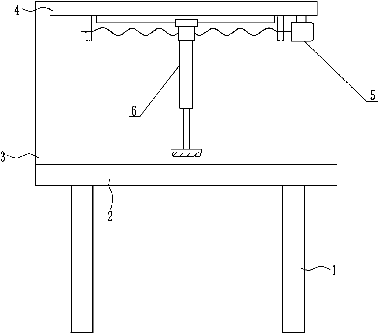
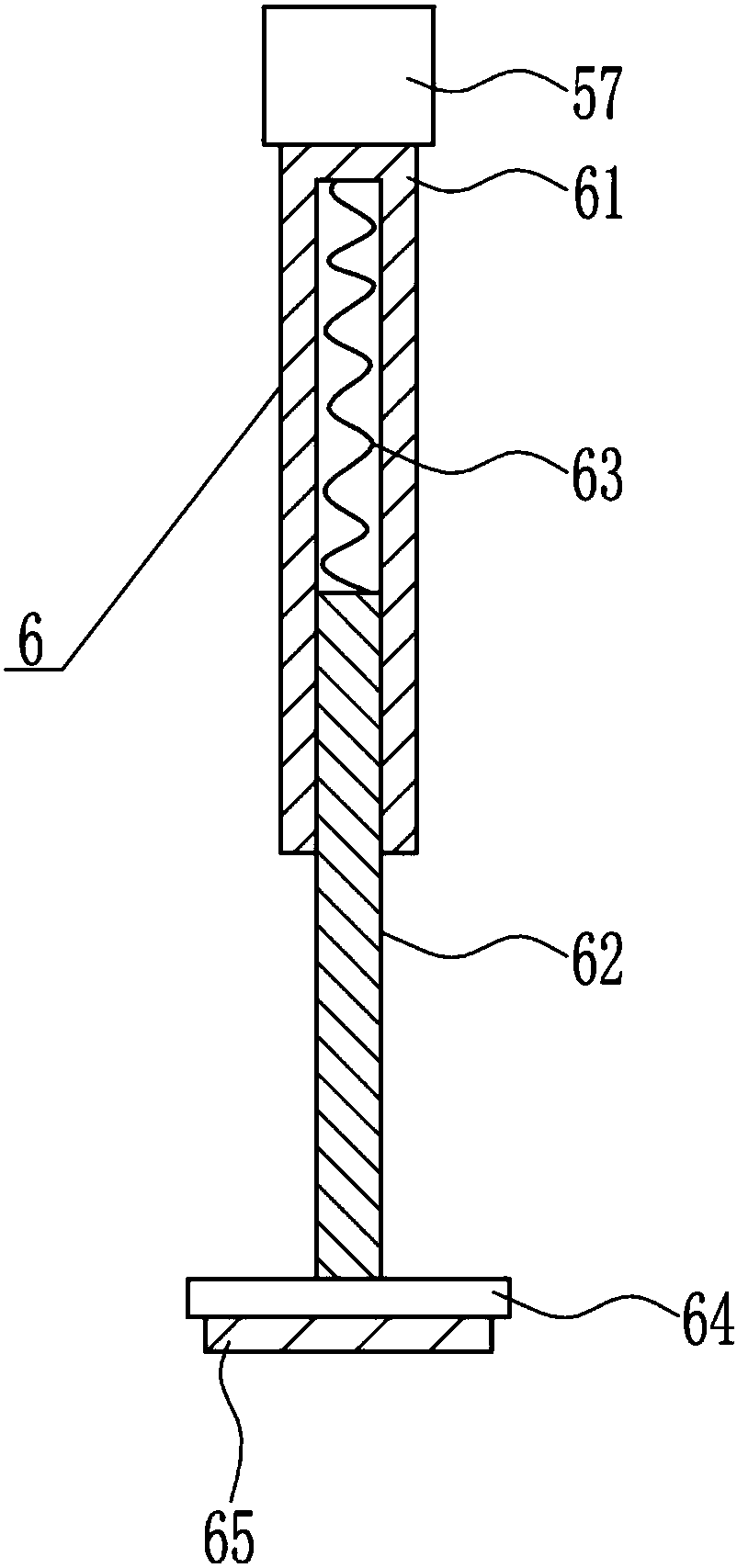
[0037] A stainless steel plate deburring equipment for power distribution cabinet production, such as Figure 1-8 As shown, it includes a support leg 1, a placement plate 2, a bracket 3, a top plate 4, a left and right moving device 5 and a deburring device 6. The top of the support leg 1 is horizontally connected with the placement plate 2 by means of bolt connection, and the top of the placement plate 2 is left The side is vertically installed with a support 3 by means of bolt connection, and the top of the right side of the support 3 is horizontally connected with a top plate 4 by means of bolt connection. Deburring device6.

Embodiment 2

[0039] A stainless steel plate deburring equipment for power distribution cabinet production, such as Figure 1-8 As shown, it includes a support leg 1, a placement plate 2, a bracket 3, a top plate 4, a left and right moving device 5 and a deburring device 6. The top of the support leg 1 is horizontally connected with the placement plate 2 by means of bolt connection, and the top of the placement plate 2 is left The side is vertically installed with a support 3 by means of bolt connection, and the top of the right side of the support 3 is horizontally connected with a top plate 4 by means of bolt connection. Deburring device6.

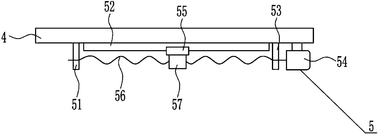
[0040] The left and right moving device 5 includes a left bearing seat 51, a slide rail 52, a right bearing seat 53, a first motor 54, a slider 55, a screw mandrel 56 and a nut 57, and the bottom of the top plate 4 is installed by bolts from left to right. There is a left bearing seat 51, a slide rail 52, a right bearing seat 53 and a first motor 54,...

Embodiment 3

[0042] A stainless steel plate deburring equipment for power distribution cabinet production, such as Figure 1-8 As shown, it includes a support leg 1, a placement plate 2, a bracket 3, a top plate 4, a left and right moving device 5 and a deburring device 6. The top of the support leg 1 is horizontally connected with the placement plate 2 by means of bolt connection, and the top of the placement plate 2 is left The side is vertically installed with a support 3 by means of bolt connection, and the top of the right side of the support 3 is horizontally connected with a top plate 4 by means of bolt connection. Deburring device6.

[0043] The left and right moving device 5 includes a left bearing seat 51, a slide rail 52, a right bearing seat 53, a first motor 54, a slider 55, a screw mandrel 56 and a nut 57, and the bottom of the top plate 4 is installed by bolts from left to right. There is a left bearing seat 51, a slide rail 52, a right bearing seat 53 and a first motor 54,...


PUM


Abstract

The invention belongs to the technical field of power distribution cabinet production, and particularly relates to deburring equipment for a stainless steel plate for power distribution cabinet production. The deburring equipment for the stainless steel plate for the power distribution cabinet production has the advantages that the manufacturing cost is low, the deburring effect is good, and the operation is easy. The deburring equipment for the stainless steel plate for the power distribution cabinet production comprises supporting legs and the like; a placement plate is horizontally connected to the tops of the supporting legs in a bolted connection mode; a support is vertically arranged on the left side of the top of the placement plate in a bolted connection mode; a top plate is horizontally connected to the top of the right side surface of the support in a bolted connection mode; and a left-right moving device is arranged at the bottom of the top plate. According to the deburringequipment, a first motor is adopted for driving abrasive paper to move left and right continuously so as to carry out deburring work on the stainless steel plate, and therefore the effects of low manufacturing cost, good deburring effect and simple operation can be achieved.

Description

technical field [0001] The invention belongs to the technical field of power distribution cabinet production, and in particular relates to a stainless steel plate deburring device for power distribution cabinet production. Background technique [0002] The link in the power system that is directly connected to the user and distributes electric energy to the user. [0003] The power distribution cabinet (box) is divided into power distribution cabinet (box), lighting distribution cabinet (box), metering cabinet (box), and is the final equipment of the power distribution system. The power distribution cabinet is a general term for the motor control center. The power distribution cabinet is used in the occasions where the load is relatively scattered and there are few circuits; the motor control center is used in the occasions where the load is concentrated and there are many circuits. They distribute the electric energy of a certain circuit of the upper-level power distribut...

Claims


Application Information

Patent Timeline
Patent Type & Authority Applications(China)
IPC IPC(8): B24B9/04B24B41/06B24B41/02B24B55/06
CPCB24B9/04B24B41/02B24B41/06B24B55/06
Inventor 郭昌磊秦洪琼蒋浩杰
Owner 郭昌磊
Why Eureka
Try Eureka