Automatic bowl filling machine and bowl filling method thereof

A pot-filling and automatic technology, which is applied in the directions of packaging, transportation and packaging, and the types of packaging items, can solve the problems of large space occupation, difficult debugging, complicated equipment structure, etc., and achieves simple and compact structure, high pot-filling efficiency, and operation low cost effect

Active Publication Date: 2018-04-20
HUNAN JINLU TECH CO LTD
View PDF7 Cites 8 Cited by
  • Summary
  • Abstract
  • Description
  • Claims
  • Application Information

AI Technical Summary

Problems solved by technology

However, for materials with bulk density requirements, using a vibrator or a flattening mechanism for leveling will squeeze out the air between the powder materials and increase the density of the materials, which cannot meet the product quality control requirements, and for materials with poor fluidity, vibration and shaking It is also difficult to achieve the flatness requirements of the material surface
At the same time, the existing bowl filling machine is divided into two processes for filling the material and leveling the surface, which has the problems of low efficiency, complex equipment structure, large space occupation, difficult debugging, and high cost.
In addition, in order to control the amount of bowl filling, the existing bowl filling equipment uses a feeding device to directly add materials into the sagger in the form of falling, and weighs through the weighing component carrying the sagger to control the amount of bowl filling. To ensure the accuracy of weighing, it is necessary to control the feeding speed of the material, and it is necessary to fix the sagger in place before feeding and weighing, which affects the efficiency of filling the bowl

Method used


Image

  • Automatic bowl filling machine and bowl filling method thereof
  • Automatic bowl filling machine and bowl filling method thereof
  • Automatic bowl filling machine and bowl filling method thereof

Examples


Embodiment Construction

[0031] The present invention will be described in further detail below in conjunction with the accompanying drawings and specific embodiments.

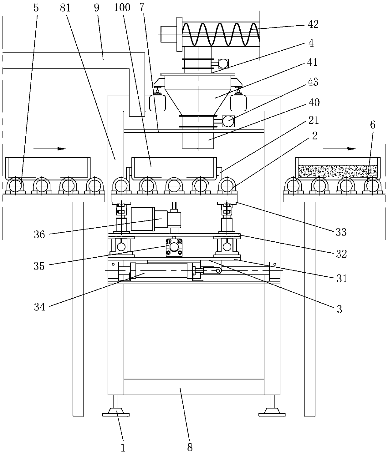
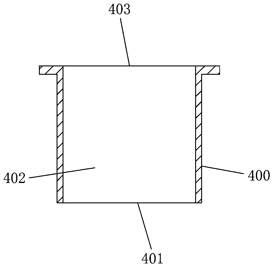
[0032] Such as Figure 1 to Figure 3 As shown, the automatic bowl loading machine of this embodiment includes a frame 1 and a loading conveyor line 2 for carrying and transporting the sagger 100, and the loading conveyor line 2 is provided with a fixing device that can loosen or fix the sagger 100 21. The loading conveying line 2 is installed on the frame 1 through a three-dimensional space displacement driving device 3. The three-dimensional spatial displacement driving device 3 can drive the horizontal and vertical translational movement of the charging conveying line 2. The machine above the charging conveying line 2 The frame 1 is equipped with a blanking device 4 that relies on the self-weight of the material for blanking. The blanking device 4 has a blanking head 40 that can be inserted into the sagger 100. The lower end surface...


PUM


Abstract

The invention discloses an automatic bowl filling machine and a bowl filling method thereof. The automatic bowl filling machine comprises a machine frame and a filling conveying line used for bearingand conveying a sagger, a fixing device capable of loosening or fixing the sagger is arranged on the filling conveying line, the filling conveying line is installed on the machine frame through a three-dimensional space displacement driving device, and a discharging device which is used for discharging materials under the action of the self weight of the materials is arranged above the filling conveying line; the discharging device is provided with a discharging head which can extend into the sagger, the lower end surface of the discharging head is parallel to the horizontal plane and is provided with more than one discharging port used for allowing the discharging device to discharge the materials; and a bowl feeding conveying line and a bowl discharging conveying line are arranged on themachine frame. The bowl filling method comprises the step of enabling the discharging head to extend into the sagger to perform discharging and leveling simultaneously by utilizing the automatic bowlfilling machine. The machine has the advantages of being simple and compact in structure, high in bowl filling efficiency, low in operation cost and good in bowl filling quality.

Description

technical field [0001] The invention relates to the technical field of powder bowl filling equipment, in particular to an automatic bowl filling machine and a bowl filling method thereof. Background technique [0002] In the production of powder materials such as cathode materials for lithium-ion batteries, the materials to be sintered must first be put into a sagger, and then sintered at a high temperature in a kiln. In order to ensure the consistency and sintering quality of the material after sintering, the amount of material loaded into the bowl, the loose packing density of the material into the bowl, and the flatness of the surface of the material in the sagger need to be precisely controlled. [0003] The existing bowl filling equipment all adopts a vibrator or a flattening mechanism to keep the surface of the material in the sagger smooth. However, for materials with bulk density requirements, using a vibrator or a flattening mechanism for leveling will squeeze out ...

Claims


Application Information

Patent Timeline
Patent Type & Authority Applications(China)
IPC IPC(8): B65B1/06B65B43/54
CPCB65B1/06B65B43/54Y02E60/10
Inventor 张勋郎欧阳建杨克辉梅志坤胡茂黄映红
Owner HUNAN JINLU TECH CO LTD
Why Eureka
Try Eureka