
Food conveying device

A technology of conveying device and food, applied in the direction of cleaning device, conveyor, conveyor objects, etc., can solve the problems of increasing production cost, affecting the appearance and quality of food, poor adaptability, etc., to save production cost, rich in functions, and flexible in use. Effect

Pending Publication Date: 2018-04-20
湖州星座食品有限公司
View PDF0 Cites 4 Cited by
  • Summary
  • Abstract
  • Description
  • Claims
  • Application Information

AI Technical Summary

Problems solved by technology

[0002] The conveying device is a mechanism used to transport food in food machinery. The existing conveying devices can only be conveyed horizontally, or conveyed to high places in an inclined shape, with single function and poor adaptability. The horizontal conveying section of the production line is rebuilt to convey to high places. At this time, the conveying device that was originally responsible for horizontal conveying in the factory area can only be idled or eliminated in vain, and corresponding conveying equipment needs to be purchased, which greatly increases production. cost, and the surface of the conveyed food is mostly adhered to the food residue, which will not only affect the appearance and quality of the food, but also will fall on the ground near the conveying device during the conveying process. The environment in the factory area is polluted. In order to keep the factory area tidy, the workers in the factory area have to clean it in time, which is time-consuming and laborious.

Method used


Image

  • Food conveying device

Examples


Embodiment Construction

[0014] The present invention is not limited by the following examples, and specific implementation methods can be determined according to the technical scheme of the present invention and actual conditions.

[0015] Below in conjunction with embodiment and accompanying drawing, the present invention will be further described:

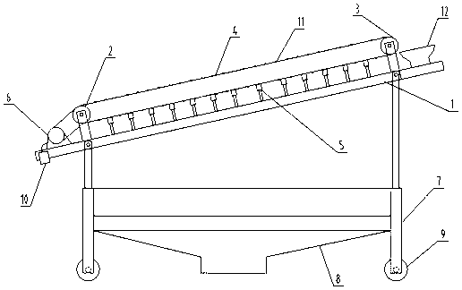
[0016] Such as figure 1 As shown, the food conveying device includes a frame 1, a left roller 2, a right roller 3, and a conveyor belt 4, and the left roller 2 and the right roller 3 are respectively rotatably fixedly installed at the left and right ends of the frame 1, The conveyor belt 4 is arranged on the left roller 2 and the right roller 3, and at least one brush 5 is fixedly installed on the frame 1 below the conveyor belt 4. The left side of the frame 1 is fixedly installed with a motor 6 that can drive the left roller 2 to rotate. The bottom of the frame 1 is hinged with four telescopic legs 7. On the legs 7 below the brush 5, there are detacha...


PUM


Abstract

The invention relates to the technical field of conveying devices, in particular to a food conveying device. The food conveying device comprises a rack, a left roller, a right roller and a conveying belt; the left roller and the right roller are rotatably and fixedly mounted at the left and right ends of the rack correspondingly; at least one brush is fixedly mounted in the position, on the lowerportion of the conveying belt, of the rack; a motor capable of driving the left roller to rotate is fixedly mounted on the left side of the rack; four telescopic supporting legs are hinged to the bottom of the rack; and a residue receiving container corresponding to the conveying belt is detachably and fixedly mounted in the position, below the brushes, of the supporting legs. The food conveying device is compact and reasonable in structure; by arranging the residue receiving container and a residue receiving bowl, food residues falling from the conveying belt can be effectively collected, thesituation that the food residues fall onto a floor and consequently the factory environment is polluted is avoided, the time and labor are saved, and the situation of sweeping the floor frequently byworkers is no longer needed; through the design that the supporting legs are telescopic, the food conveying device can be adjusted to be in a horizontal conveying mode or an inclined conveying mode,so that using is more flexible, the functions are richer, and the production cost can be saved greatly.

Description

technical field [0001] The invention relates to the technical field of conveying devices, in particular to a food conveying device. Background technique [0002] The conveying device is a mechanism used to transport food in food machinery. The existing conveying devices can only be conveyed horizontally, or conveyed to high places in an inclined shape, with single function and poor adaptability. The horizontal conveying section of the production line is rebuilt to convey to high places. At this time, the conveying device that was originally responsible for horizontal conveying in the factory area can only be idled or eliminated in vain, and corresponding conveying equipment needs to be purchased, which greatly increases production. cost, and the surface of the conveyed food is mostly adhered to the food residue, which will not only affect the appearance and quality of the food, but also will fall on the ground near the conveying device during the conveying process. The envi...

Claims


Application Information

Patent Timeline
IPC IPC(8): B65G23/04B65G45/18B65G41/00B65G45/26
CPCB65G23/04B65G41/005B65G41/008B65G45/18B65G45/26B65G2201/0202
Inventor 慎菁菁
Owner 湖州星座食品有限公司
Learn More