[0032] In order to make the objectives, technical solutions and advantages of the present invention clearer, the following further describes the present invention in detail with reference to the accompanying drawings and embodiments. The specific embodiments described here are only used to explain the present invention, but not to limit the present invention. In addition, the technical features involved in the various embodiments of the present invention described below can be combined with each other as long as they do not conflict with each other.
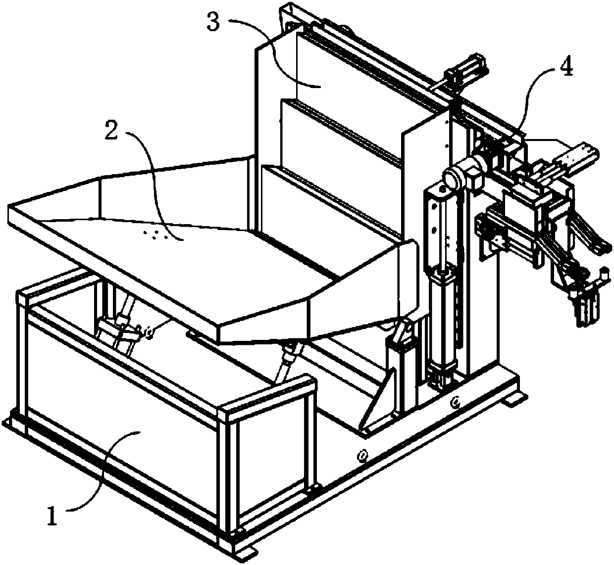
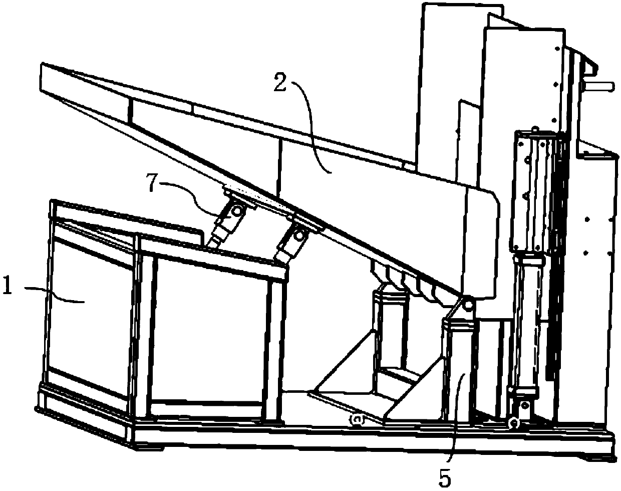
[0033] Such as figure 1 As shown, the disordered feeder applying the material dividing and positioning device of the present invention includes a bracket 1, a bin 2, a feeding mechanism 3, and a material dividing and positioning device 4. The bracket 1, the silo 2, and the feeding mechanism 3 are the main components of the ladder feeding device, such as Picture 10 As shown, the stepped feeding device is connected to the distributing positioning device 4 through an inclined discharge plate 419 arranged at its discharge port.
[0034] Such as figure 2 As shown, the bracket 1 of the step feeding device includes a base and columns 5 fixed on both sides of the base. The middle of the bottom surface of the silo 2 is hinged with the base of the bracket 1 through a cylinder b7, and the bottom of one end of the outlet of the silo 2 is connected to the base through a rotating shaft. Column 5 is hinged.
[0035] Such as image 3 As shown, the material distribution and positioning device 4 includes a transmission mechanism 401, a material distribution mechanism, a material shifting mechanism 404, a material pushing device 405, a positioning device 406, and a material blocking device 407.
[0036] Such as Figure 4 , 5 As shown, the transmission mechanism 401 includes an upper transmission channel 409 and a lower transmission channel 410 arranged in parallel below the upper transmission channel. The upper transmission channel 409 is in contact with the bottom of the discharge plate 419, and both ends of the lower transmission channel 409 are longer than the upper transmission channel 410. The upper conveying lane 409 and the lower conveying lane 410 are both conveyed by a conveying belt, and baffles are arranged around the conveying belt to shield the workpiece 8. The end of the upper transmission lane 409 is provided with a stopper 408, and the bottom of the stopper 408 is fixedly connected to the top of the baffle of the lower transmission lane 410. A gap is formed between the stopper 408 and the end of the upper transmission lane 409 for the workpiece 8 to fall to The blanking space 411 of the lower conveyor 410.
[0037] Such as Image 6 with 7 As shown, the material distribution mechanism includes a first material channel 402 and a second material channel 403, and the first material channel 402 and the second material channel 403 are respectively arranged at both sides of the bottom end of the lower conveying channel 410. The first forehearth 402 and the second forehearth 403 are along the front section and the rear section in the length direction, wherein the front section is horizontal, and the rear section forms an angle with the front section and is inclined downward. The first material channel 402 and the second material channel 403 are provided with a slide 403a for feeding along the length direction. After the workpiece 8 falls into the slide 403a, its small end can pass through the slide 403a, and the large end is stuck in the slide 403a The upper end surface. Each of the bottoms of the first material channel 402 and the second material channel 403 is provided with a pushing device 405, and the pushing device 405 includes a second air cylinder 405a and a pushing plate 405b. The upper part of the pusher plate 405b passes through the slideway 403a, and the lower part is fixedly connected to the second cylinder 405a. The pusher plate 405b can reciprocate along the slideway 403a under the drive of the second cylinder 405a, so that the workpiece 8 falling into the slideway 403a Push to the rear section of the slide 403a, and the workpiece 8 slides along the inclined rear section to the end of the slide 403a.
[0038] Such as Picture 8 with 9 As shown, the material shifting mechanism 404 is arranged above the end of the transmission mechanism 401. The material shifting mechanism 404 can reciprocate in a direction perpendicular to the transmission mechanism 401 under the drive of an air cylinder, and will reciprocate the lower transmission channel 410 during the reciprocating motion. Adjacent workpieces 8 are allocated to the first material channel 402 and the second material channel 403. The material shifting mechanism 404 includes a material shifting head 414 for distributing adjacent workpieces 8 to the first forehearth 402 and the second material channel 403, a first air cylinder 413 for controlling the reciprocating movement of the material shifting head 414, and a material shifting mechanism Install bracket 412. The material shifting mechanism mounting bracket 412 is installed on the retaining wall of the lower transmission channel 410, the first air cylinder 413 is horizontally fixed on the material shifting mechanism mounting bracket 412, and its end is fixedly connected with the material shifting head 414. The material shifting head 414 includes a material shifting plate 414c, a fixing plate 414b, a side baffle 414d, and an upper pressing plate 414a. The upper pressing plate 414a is arranged horizontally, and the fixing plate 414b and the material shifting plate 414c are vertically fixed on the upper and lower surfaces of the upper pressing plate 414a. On the surface. The fixing plate 414b is fixedly connected with the first air cylinder 413, and the side baffle 414d is arranged on one side of the upper pressing plate 414a and vertically fixedly connected with the upper pressing plate 414a and the material shifting plate 414c. When the first air cylinder 413 contracts, the workpiece falls to the second forehearth 403 under the action of the material shifting plate 414c. When the first air cylinder 413 is extended, the adjacent workpieces behind the workpiece fall under the action of the material shifting plate 414c. Fall to the first material channel 402.
[0039] Such as Picture 11 with 12 As shown, the blocking device 407 includes a supporting frame 416, a third cylinder 415, a blocking frame 417, and an upper blocking plate 418. Both ends of the upper baffle plate 418 are horizontally fixed above the baffle frame 417 by brackets, and the level of the bottom of the upper baffle plate 418 is higher than the surface of the uppermost workpiece of the step feeding device. The support frame 416 is fixed on the side wall of the upper transmission channel 409. The third cylinder 415 is arranged horizontally and one end of the cylinder is fixedly connected to the support frame 416, and the other end is fixedly connected to the stop frame 417. When the third cylinder 415 is in an extended state At this time, the front end of the stopper frame 417 abuts against the discharge port of the step feeding device to prevent the workpiece from falling onto the upper conveying lane 409. The baffle frame 417 includes a front plate 417a, a rear plate 417b, a side plate 417c, and a bottom plate 417d that are fixedly connected to form a frame-like structure. The front plate 417a and the rear plate 417b are fixedly connected by a reinforcing plate 417e.
[0040] Such as Figure 13 with 14 As shown, the positioning device 406 includes a lifting platform 406a, a positioning sleeve 406b fixed at both ends of the lifting platform 406a for posture correction of the workpiece 8, and a positioning device fixing bracket 406c for fixing the positioning device 406, and a positioning device fixing bracket 406c It is fixed on the end baffle of the lower transmission lane 410. The positioning sleeve 406b includes two locating sleeves, which are respectively arranged directly below the ends of the slideways of the first forehearth 402 and the second forehearth 403. The center of the positioning sleeve 406b is provided with a cavity, the upper part of the cavity is a conical guide cavity 406b1, and the lower part is a cylindrical limiting cavity 406b2. Among them, the lifting platform 406a is a lifting bracket driven by an air cylinder.
[0041] Such as Figure 15 with 16 As shown, the feeding mechanism 3 includes a fixed plate group 303 fixed vertically and a movable washboard group 304 for conveying workpieces upward. The movable washboard group 304 can move up and down relative to the fixed plate group 303. The movable washboard group 304 and the fixed plate The top of the group 303 is provided with a workpiece bearing surface 302 that can be connected to each other. The movable washboard group 304 includes a plurality of movable washboards 304a arranged evenly in parallel, and the fixed board group 303 includes a plurality of fixed boards 303a arranged evenly in parallel. The movable washboard 304a and the fixed board 303a are arranged at intervals. The movable washboard group 304 includes a low position and a high position. When the movable washboard group 304 is in the low position, the bearing surface 302 of the movable washboard 304a is connected with the bearing surface 302 of the adjacent fixed plate 303a on the side facing the silo. When the movable washboard group 304 is in the high position, the movable washboard 304a The bearing surface 302 of the silo is connected with the bearing surface 302 of the adjacent fixed plate 303a on the side away from the silo. The bearing surfaces 302 of the movable rubbing plate group 304 and the fixed plate group 303 are inclined surfaces with one end facing the silo 2 higher than the other end. A side plate 301 is provided on both sides of the feeding mechanism 3, two ends of the movable washboard group 304 are fixedly connected to the side plate 301, and the side plate 301 is movably connected to the bracket 1 through a vertically arranged cylinder a6.
[0042] The working principle of this device is as follows: when the movable washboard group 304 is in the low position, the workpiece is rolled from the silo 2 to the movable washboard 304a of the feeding mechanism 3. The movable washboard 304a is driven by the cylinder a6 and moves upward with the side plate 301 When the movable washboard 304a moves to the high position, the workpiece rolls into the bearing surface of the fixed plate 303a connected to it, and the movable washboard group 304 continues to move downwards. When it is in the low position, it is only transported to the upper stage of the fixed plate bearing surface The workpiece is rolled onto the bearing surface of the moving washboard of the next stage, and continues to move upwards, reciprocating in this way, until the workpiece is transported to the highest stage of the entire feeding mechanism 3. When the workpiece 8 is sent to the top of the entire feeding mechanism 3, it is blocked from the side by the stopper 407. When the stopper 407 is retracted, the workpiece 8 falls onto the upper conveying path 409 of the conveying mechanism 401 via the discharge plate 419 , And fall through the blanking space 411 to the lower conveyor 410. When the workpiece is conveyed to the end of the lower conveying lane 410, it is transferred to the first forehearth 402 and the second forehearth 403 by the shifting mechanism 404, and the workpiece is moved to the first forehearth 402 and the The end of the second chute 403. The lifting platform 406a of the positioning device 406 rises upward, and the positioning sleeve 406b moves upward from the bottom of the workpiece. The workpiece is guided by the conical guide cavity 406b1 and then inserted into the cylindrical limit cavity 406b2. When the positioning sleeve 406b is separated from the workpiece, the posture of the workpiece is in a standard posture, waiting for the robot to grab it.
[0043] The above are only specific embodiments of the present invention. It should be pointed out that any changes or substitutions that can be easily conceived by those skilled in the art within the technical scope disclosed by the present invention should be covered by the protection scope of the present invention. within.