
Air supply system for lime kiln

An air supply system and air supply technology, applied in the field of lime kiln, can solve the problems of small central air volume, low lime quality, deterioration, etc., and achieve the effect of uniform air supply

Active Publication Date: 2018-04-20
HENAN ZHONGHENG IND FURNACE ENG TECH
View PDF2 Cites 1 Cited by
  • Summary
  • Abstract
  • Description
  • Claims
  • Application Information

AI Technical Summary

Problems solved by technology

[0002] During the calcination process of the lime kiln, the size and uniformity of the air volume in the kiln directly affect the raw and over-burned rate of the burnt lime, which is the key to determine the output and quality of the lime. Overburning occurs in large places, and raw burning occurs in places with low wind, resulting in unstable lime production and low lime quality
[0003] In the usual lime kiln air supply system, the fan directly enters the kiln through the air supply pipe. There is a simple tower-shaped air cap connected to the air supply pipe in the kiln. This air cap mainly plays the role of preventing lime from entering the air supply pipe, so that The structure of the air supply device is simple, and it does not consider that after the wind directly enters the pipeline, due to factors such as large wind pressure and changes in the angle of the air supply pipeline, the wind will become uneven in the air supply pipeline after encountering pipeline resistance. The change of air flow caused by the resistance generated after meeting the material in the kiln will cause the air volume to be less at the top near the air cap, the air volume in the center is small, and the air supply is uneven. This air supply method will easily block the air supply pipe after long-term production and cause air supply With the further deterioration of the situation, there is an urgent need for a lime kiln air supply system to overcome the above disadvantages

Method used


Image

  • Air supply system for lime kiln
  • Air supply system for lime kiln

Examples


Embodiment 1

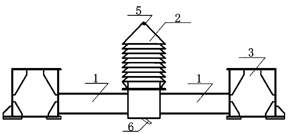
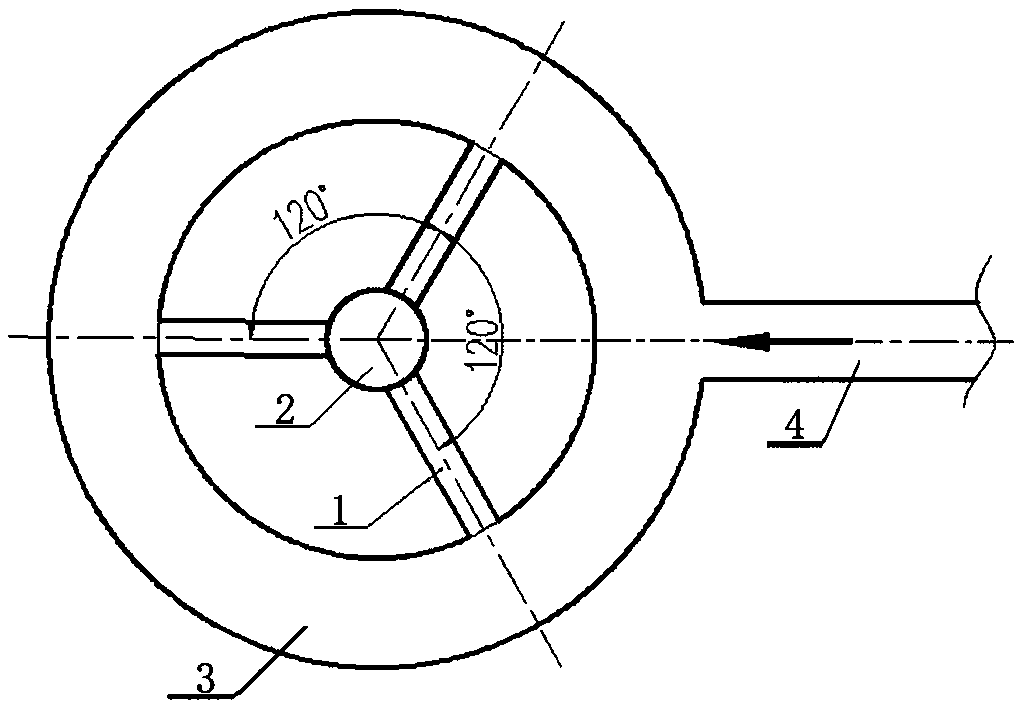
[0019] A kind of lime kiln air supply system of the present invention, as Figure 1~2 As shown, it includes an exhaust fan, an air supply pipeline 4, and an air collecting box 3, and the exhaust fan is fixedly connected with the air supply pipeline 4, and the described air collecting box 3 is circular, and the air collecting box 3 is fixedly connected with the air supply pipeline 4, Three air supply branch pipes 1 are provided on the circular inner wall of the air collection box 3, and the included angles between the three air supply branch pipes 1 are all 120°, and the other ends of the three air supply branch pipes 1 are intersected with a wind cap 2 , the hood 2 is a multi-layer tower structure with the same diameter, and each layer of the hood 2 is evenly arranged with a plurality of air supply holes every week, and each layer of the hood 2 is evenly arranged with a plurality of air outlets every week; the hood 2 is A 10-story tower structure with the same diameter; the to...


PUM


Abstract

The invention relates to the technical field of the lime kiln and discloses an air supply system for the lime kiln. The air supply system comprises an exhaust fan, an air supply pipeline and an air collection tank, the exhaust fan is fixedly connected with the air supply pipeline, the air collection tank is ring-shaped, the air collection tank and the air supply pipeline are fixedly connected, three air supply branch pipes are formed in the ring-shaped inner wall of the air collection tank, the included angles among the three air supply branch pipes are 120 degrees, and an air cap is arrangedon the intersection part of the other ends of the three air supply branch pipes. The air cap is in a tower-shaped structure, the diameters of the multiple layers of the tower-shaped structure are thesame, a plurality of air supply holes are evenly distributed at each periphery of each layer of the air cap, and a plurality of air outlets are evenly distributed at the periphery of each layer of theair cap. The air cap is in the tower-shaped structure, and the diameters of the ten layers of the tower-shaped structure are the same. A dust falling groove is distributed at the top part of the aircap, and a dust leading pipe is distributed at the lower part of the air cap. The air supply system overcomes the defect of uneven air supply of the lime kiln existing for a long period of time.

Description

technical field [0001] The invention relates to the technical field of lime kilns, in particular to a lime kiln air supply system. Background technique [0002] During the calcination process of the lime kiln, the size and uniformity of the air volume in the kiln directly affect the raw and over-burned rate of the burnt lime, which is the key to determine the output and quality of the lime. Overburning occurs in large places, and raw burning occurs in places with low wind, resulting in unstable lime production and low lime quality. [0003] In the usual lime kiln air supply system, the fan directly enters the kiln through the air supply pipe. There is a simple tower-shaped air cap connected to the air supply pipe in the kiln. This air cap mainly plays the role of preventing lime from entering the air supply pipe, so that The structure of the air supply device is simple, and it does not consider that after the wind directly enters the pipeline, due to factors such as large w...

Claims


Application Information

Patent Timeline
IPC IPC(8): C04B2/12
CPCC04B2/12
Inventor 李威
Owner HENAN ZHONGHENG IND FURNACE ENG TECH
Learn More