Adjustable bridge rail support

An adjustable technology for bridge bearings, applied in bridges, bridge parts, bridge construction, etc., can solve problems such as uneven stress, cracking, and non-recoverability

Pending Publication Date: 2018-04-20
CHANGSHA UNIVERSITY OF SCIENCE AND TECHNOLOGY +1
View PDF6 Cites 10 Cited by
  • Summary
  • Abstract
  • Description
  • Claims
  • Application Information

AI Technical Summary

Problems solved by technology

[0004] The present invention aims to solve the problem that under the action of external loads (such as temperature loads), the structure of the existing bridge supports tends to have large longitudinal and transverse unrecoverable displacements, resulting in voids and uneven stress on the supports of the bridge structure, resulting in bridge failure. Provide an adjustable bridge rail support structure to prevent fatigue, cracking and other series of problems in surface pavement

Method used


Image

  • Adjustable bridge rail support
  • Adjustable bridge rail support
  • Adjustable bridge rail support

Examples


Embodiment Construction

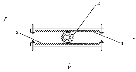
[0015] see Figure 1 to Figure 3 , the steel-concrete composite structure bridge support includes an upper track plate 1, a lower track plate 3 through which the gear shaft 2 and the upper track plate 1 are mechanically transmitted.

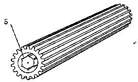
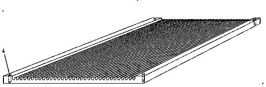
[0016] Preferably, positioning bolt holes 4 are provided around the upper track plate 1 , and the upper track plate 1 is connected to the main beam through studs passing through the positioning bolt holes 4 . Positioning bolt holes 4 are also provided around the lower track plate 3 , and the lower track plate 3 is connected to the supporting structure through studs passing through the positioning bolt holes 4 . The gear shaft 2 is a roller with gears. The two ends of the central shaft of the gear shaft 2 are provided with locking grooves 5 , and the gear shaft 2 is connected with the external power mechanism through the locking grooves 5 .


PUM


Abstract

The invention discloses an adjustable bridge rail support comprising an upper rail board and a lower rail board which performs mechanical transmission with the upper rail board via a gear shaft. The steel-concrete composite structure bridge support of the present invention effectively solves the problems of existing steel-concrete composite structure bridge bearings under external load, falling off of roof, overrun of vertical displacement, and limited angle of rotation at locals of girders so that the stress of the steel-concrete composite structure is uneven, and the technical problems suchas fatigue, cracking, and the like of the bridge deck pavement are prone to occur.

Description

technical field [0001] The invention relates to an adjustable bridge rail support. Background technique [0002] A large amount of technical statistical data has found that the existing bridges (especially steel bridges and curved bridges) have typical defects such as empty space, displacement exceeding the limit, and rotation angle exceeding the limit. Curved bridges (or steel bridges) are prone to unrecoverable longitudinal and lateral displacements under temperature loads, resulting in voids in the supports and cracks in the bridge deck, which pose great hidden dangers to structural safety, not only affecting driving The patency and comfort of the car also bring huge hidden dangers to safety and durability. [0003] The study found that the current main factors leading to bearing diseases mainly include three aspects: construction, maintenance, and external loads. Over the years, with the continuous development of engineering technology, the continuous improvement of th...

Claims


Application Information

Patent Timeline
Patent Type & Authority Applications(China)
IPC IPC(8): E01D19/04
CPCE01D19/043E01D19/048
Inventor 王达张有举施军军陈方怀刘旺刘扬
Owner CHANGSHA UNIVERSITY OF SCIENCE AND TECHNOLOGY
Why Eureka
Try Eureka