Shifting device and method of existing building

A shifting device and technology for existing buildings, applied in construction, building maintenance, building construction, etc., can solve the problems of low construction efficiency, time-consuming, cumbersome process, etc., to alleviate the impact of horizontal jacks, facilitate installation or The effect of adjusting and simplifying the process of shifting

Active Publication Date: 2018-04-20
SHANGHAI NO 4 CONSTR
View PDF5 Cites 5 Cited by
  • Summary
  • Abstract
  • Description
  • Claims
  • Application Information

AI Technical Summary

Problems solved by technology

This kind of displacement technology needs to install a large track beam at the lower part of the pallet beam, and the flatness of the track beam is also particularly high. At the same time, the building displacement can only be translated in one direction. Adjusting the jacking direction is a cumbersome process, and the construction and design costs are relatively high. In addition, it usually takes a lot of time to install steel pads to supplement the insufficient jacking stroke of the power equipment during the building shifting process. The construction efficiency is relatively low and wasteful a lot of time

Method used


Image

  • Shifting device and method of existing building
  • Shifting device and method of existing building
  • Shifting device and method of existing building

Examples


Embodiment 1

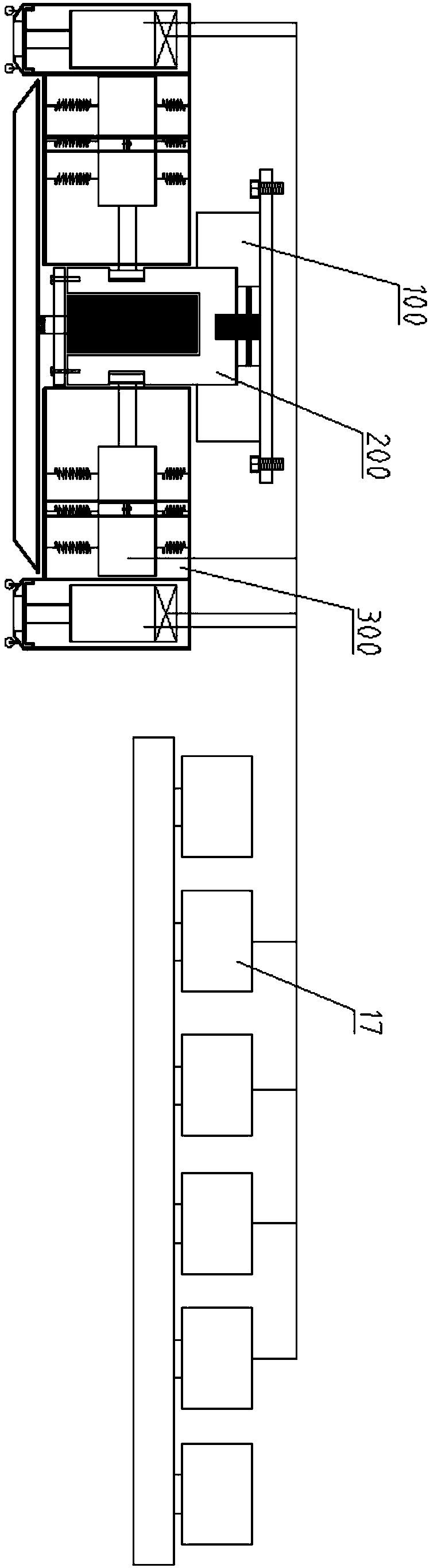
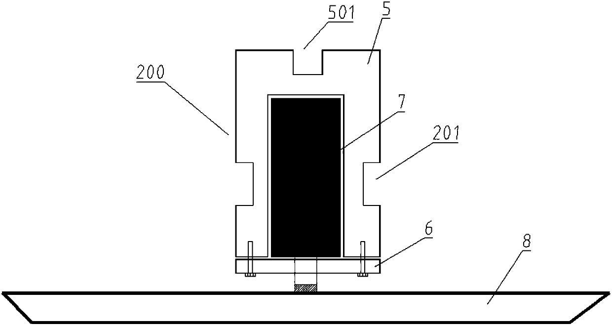
[0048] This embodiment provides a displacement device for existing buildings, such as Figure 1-15As shown, it includes a connection mechanism 100 connected to the bottom of an existing building, a displacement drive mechanism 300 for driving the connection mechanism 100 to move, and a jacking mechanism 200 for connecting the connection mechanism 100 and the displacement drive mechanism 300 .

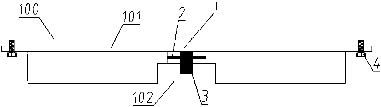
[0049] The connection mechanism 100 includes a base 1, a flange 101 is provided on the side of the base 1 close to the existing building, and a connecting bolt 4 is provided on the flange 101 to fix the base 1 to the bottom of the existing building.

[0050] In the middle of the base 1 is rotatably provided a rotating disk 2 whose axis extends vertically, and a rotating shaft 3 is coaxially fixed on the rotating disk 2. The rotation of the rotating disk 2 is driven by a motor connected to a computer control system 17. , and furthermore, the rotation and rotation angle of the rotation sh...

Embodiment 2

[0066] Embodiment 2 is directed at the use method of the shifting device in Embodiment 1, which specifically includes the following steps:

[0067] Step 1: Underpinning construction is required before the existing building is moved to place the existing building on the pallet, and set the anchor plate on the lower side of the pallet;

[0068] Step 2: leveling the shifting site of the existing building, and laying steel plates on the leveled site, the steel plate is a stainless steel plate to reduce the friction with the shifting shoe 8;

[0069] Step 3: Determine the displacement route of the existing building according to the starting point and end point of the displacement, and determine the position of the lock hole 22 according to the maximum stroke of the horizontal jack 12, and bury the lock hole 22 in the site; The coordinates are input into the computer control system;

[0070] Step 4: Install a plurality of shifting devices as required. The installation sequence of e...


PUM


Abstract

The invention provides a shifting device and method of an existing building. The shifting device comprises a connection mechanism capable of being fixed to the bottom of the existing building and twosets of shifting driving mechanisms used for driving the connection mechanism to shift in the shifting direction. Each shifting driving mechanism comprises a box, an axial line fixed to the interior of the box, a horizontal jack and a fixing jack, wherein the horizontal jack and the fixing jack are parallel to the shifting direction. An extending rod of each horizontal jack extends out from one side, away from the corresponding fixing jack, of the box, an extending rod of each fixing jack extends out from the lower side of the box, the extending rods of the horizontal jacks of the two sets ofshifting driving mechanisms are arranged in the opposite directions, and both the horizontal jacks and the fixing jacks are double-acting jacks. The shifting device can achieve multiple functions of continuous shifting, alternate jacking and the like through cooperation of the two sets of shifting driving mechanisms, the construction efficiency is improved, and meanwhile, the shifting device has the advantages that a rail is not needed, and the shifting device can rotate and shift horizontally in any direction.

Description

technical field [0001] The invention relates to the field of displacement of existing buildings, in particular to a displacement device and method for existing buildings. Background technique [0002] The existing building displacement is mainly to use the principle of underpinning to underpin the displaced building to the pallet beam, then construct a large track beam according to the displaced position, place a sliding device between the pallet beam and the track beam, and finally place a sliding device on the tray beam The front or aft position uses power equipment to apply power to slide the pallet and superstructure along the track to a new position. This kind of displacement technology needs to install a large track beam at the lower part of the pallet beam, and the flatness of the track beam is also particularly high. At the same time, the building displacement can only be translated in one direction. Adjusting the jacking direction is a cumbersome process, and the c...

Claims


Application Information

Patent Timeline
Patent Type & Authority Applications(China)
IPC IPC(8): E04G23/06
CPCE04G23/06
Inventor 谷志旺张铭孙沈鹏蔡观生何娇张波王伟茂陈雪峡
Owner SHANGHAI NO 4 CONSTR
Why Eureka
Try Eureka